Multi-carrier communication system, multi-carrier receiver apparatus and multi-carrier transmitter apparatus

a communication system and receiver technology, applied in the direction of orthogonal multiplex, power management, wireless commuication services, etc., can solve the problems of increasing interference with other stations, excessive power reception of receiving stations, unnecessarily decreasing cell capacitance, etc., to reduce individual quality value variation

Inactive Publication Date: 2005-03-10
KK TOSHIBA
View PDF3 Cites 46 Cited by
  • Summary
  • Abstract
  • Description
  • Claims
  • Application Information

AI Technical Summary

Benefits of technology

[0009] In order to achieve the above object, the present invention provides a multi-carrier transmission system having a transmitter for sending a multi-carrier signal including a plurality of sub-carrier signals and a receiver for receiving the multi-carrier signal, the receiver comprising: measuring unit configured to measure a total quality value of a multi-carrier signal received and individual quality values of sub-carrier signals included in the multi-carrier signal; first control information generating unit configure to generate first control information so as to reduce a variation of the individual quality values, for each of the sub-carrier signal; second control information generating unit configure to generate second control information so as to match the total quality value to a reference value; and notifying unit configure to notify the first control information and second control information to the transmitter; the transmitter comprising: individual power control unit configure to control individual powers of the sub-carrier signals included in the multi-carrier signal to be sent according to the first control information, while maintaining at constant a total power of the multi-carrier signal to be sent; and total power control unit configure to control the total power of the multi-carrier signal to be sent, according to the second control information.

Problems solved by technology

In such a situation, when the lowered carrier power only is put under control at the transmitting station, the receiving station is to receive power excessively.
Namely, transmission power becomes excessive at the transmitting station, resulting in a fear to cause unnecessarily cell capacitance decrease and to increase interference with other stations.

Method used


Image

  • Multi-carrier communication system, multi-carrier receiver apparatus and multi-carrier transmitter apparatus
  • Multi-carrier communication system, multi-carrier receiver apparatus and multi-carrier transmitter apparatus
  • Multi-carrier communication system, multi-carrier receiver apparatus and multi-carrier transmitter apparatus

Examples


first embodiment

[0017] (First Embodiment)

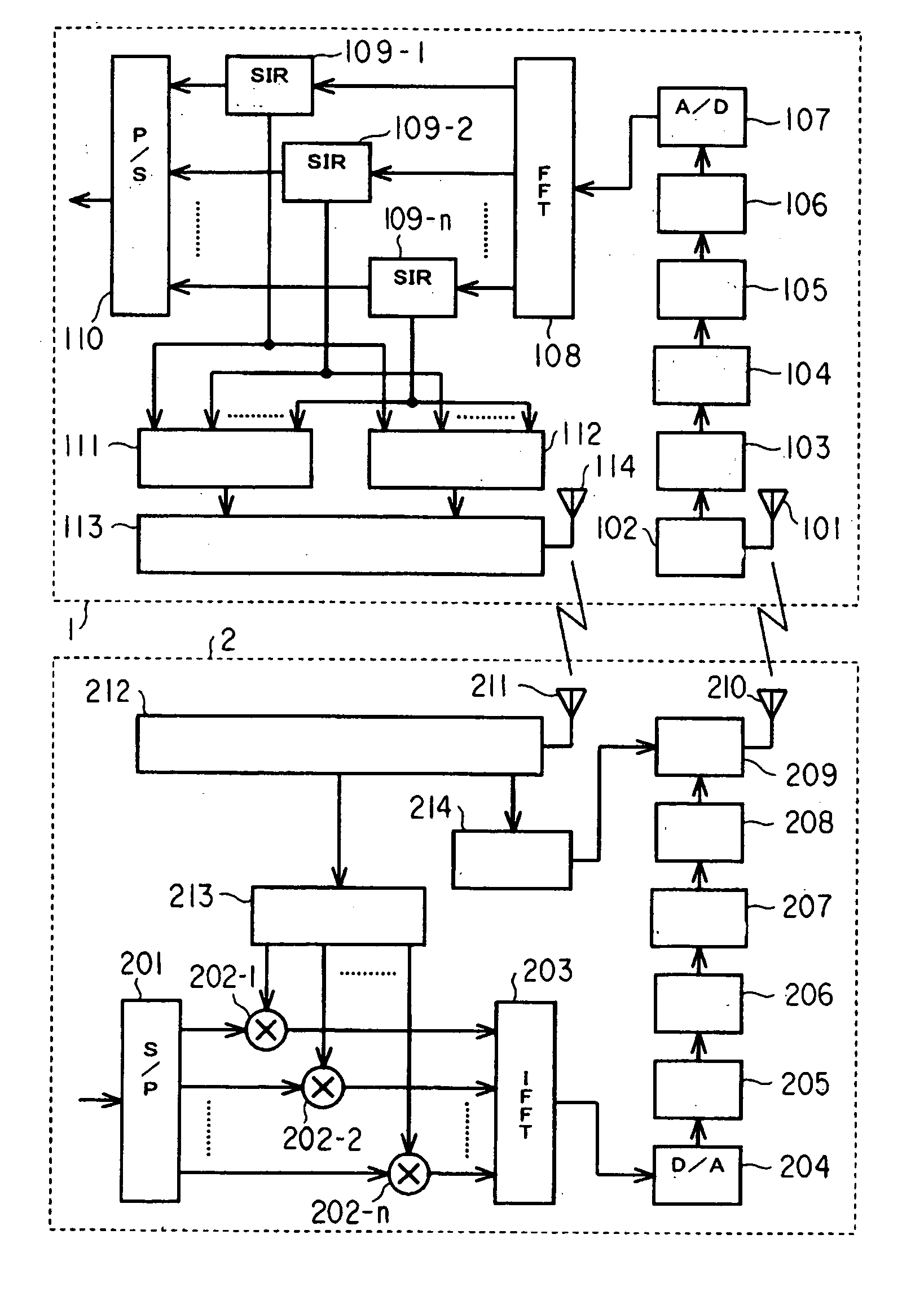
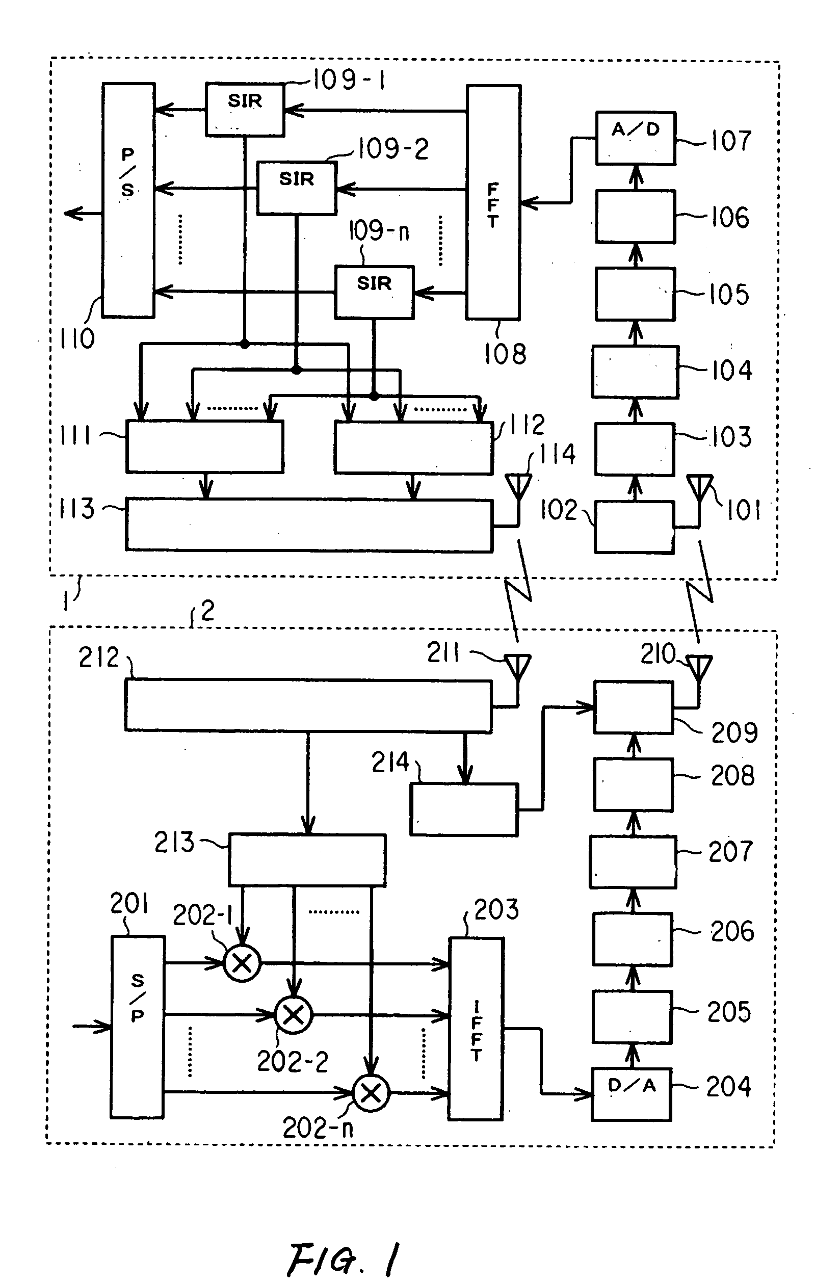
[0018]FIG. 1 is a block diagram of a multi-carrier communication system according to a first embodiment.

[0019] The multi-carrier communication system shown in FIG. 1 includes two radio apparatuses 1, 2, to wirelessly send a multi-carrier signal from the radio apparatus 2 to the radio apparatus 1.

[0020] The radio apparatus 1 includes a reception antenna 101, an amplifier 102, a filter 103, a down-converter 104. a filter 105, an amplifier 106, an A / D converter 107, a high-speed Fourier transformer (hereinafter, referred to as FFT) 108, SIR measuring sections 109-1, 109-2 . . . 109-n, a P / S converter 110, a first command generating section 111, a second command generating section 112, a transmitter system 113 and a transmission antenna 114.

[0021] The multi-carrier signal radiated as a radio wave from the radio apparatus 2 is converted into an electric signal by the reception antenna 101 and inputted to the amplifier 102. The amplifier 102 amplifies the input...

second embodiment

[0058] (Second Embodiment)

[0059]FIG. 4 is a block diagram of a multi-carrier communication system according to a second embodiment. Incidentally, the elements like those of FIG. 1 are attached with like references, to omit the detailed explanation thereof.

[0060] The multi-carrier communication system shown in FIG. 4 includes two radio apparatuses 3, 4, to wirelessly send a multi-carrier signal from the radio apparatus 4 to the radio apparatus 3.

[0061] The radio apparatus 3 includes a reception antenna 101, an amplifier 102, a filter 103, a down-converter 104. a filter 105, an amplifier 106, an A / D converter 107, an FFT 108, SIR measuring sections 109-1, 109-2 . . . 109-n, a P / S converter 110, a second command generating section 112, a transmission antenna 114, an SIR information generating section 301 and a transmitter system 302. Namely, the radio apparatus 3 has the SIR information generating section 301 and transmitter system 302 in place of the first command generating section...


PUM


Abstract

Transmission/reception power can be controlled properly. At a radio apparatus, SIR measuring sections measure individual SIRs of sub-carriers included in a multi-carrier signal received at radio apparatus. A first command generating section generates a first command representative of whether to increase, to decrease or maintain as it is the individual power for decreasing a variation of individual SIRs. A second command generating section calculates a total SIR and generates a second command for matching the total SIR to a reference value. At a transmitter apparatus, under control of a individual-power control section, gain control section controls individual powers according to the first command while maintaining at constant the total power of the multi-carrier signal to be sent. Under control of a total-power control section, an amplifier controls the total power of the multi-carrier signal according to the second command.

Description

BACKGROUND OF THE INVENTION [0001] 1. Field of the Invention [0002] The present invention relates to a multi-carrier communication system, multi-carrier receiver apparatus and multi-carrier transmitter apparatus for wirelessly sending a multi-carrier signal using a multiplicity of sub-carriers. [0003] 2. Description of the Related Art [0004] There is known a technology for improving the performance also in respect of frequency-selective fading by carrying out transmission power control on a carrier-by-carrier basis, as an art concerning transmission power control in multi-carrier communications utilizing OFDM (Orthogonal Frequency Division Multiplex). [0005] It is known that a combination of power control of the sub-carriers of a multi-carrier and power control of the entire multi-carrier modulated is used in multi-carrier communication system. This approach is disclosed in Japanese laid open (Kokai) JP-A-5-268178. This approach improves the performance, as to frequency-selective fa...

Claims


Application Information

Patent Timeline
Patent Type & Authority Applications(United States)
IPC IPC(8): H04J11/00H04B1/04H04B7/005H04W52/34
CPCH04L5/0007H04L27/2626Y02B60/50H04W52/346H04L27/2647
Inventor TAKEDA, DAISUKE
Owner KK TOSHIBA
Why Eureka
Try Eureka