Devices and methods for percutaneously treating aortic valve stenosis

a technology for aortic valves and stenosis, which is applied in the field of devices and methods for percutaneous treatment of aortic valve stenosis, can solve the problems of reducing cardiac output, affecting the treatment effect, so as to increase the flow of aortic valves and improve the treatment

Inactive Publication Date: 2005-03-10
CORDIS CORP
View PDF8 Cites 56 Cited by
  • Summary
  • Abstract
  • Description
  • Claims
  • Application Information

AI Technical Summary

Benefits of technology

[0010] Devices and methods for their use in percutaneously increasing the aortic valve flow of a stenotic aortic valve are provided. The subject devices include an aortic valve isolation element, a shunt element and an aortic valve flushing element. The aortic valve isolation element is made up of a ventricular side aortic valve occlusion element and a proximal side aortic valve isolation element. The shunt element is made up of a shunt lumen that includes one or more ventricular side blood inflow ports and one or more proximal side valves that provide for one-way exit of blood from the shunt lumen into the aorta. The aortic valve flushing element is made up of a fluid introducing element and a fluid removal element. In practicing the subject methods, a stenotic aortic valve is first isolated. Next, the isolated valve is flushed with a dissolution fluid, e.g., an acidic dissolution fluid, for a period of time sufficient for the aortic valve flow of the treated valve to be increased. In certain embodiments, the valve is also contacted with a dissolution fluid attenuating fluid, e.g., a buffer, during or after the flushing step in order to limit the contact of non-valve tissue with the dissolution fluid. Also provided are systems and kits that include the subject devices and can be employed in practicing the subject methods. The subject devices, methods, systems and kits find use in treating conditions associated with the presence of stenotic aortic valves.

Problems solved by technology

While aortic valve stenosis can results from the presence of a bicuspid valve or rheumatic fever, wear and tear of the aortic valve in the elderly is the most common cause of this condition.
Once valve leaflet mobility is reduced by calcification, turbulence across the valve increases, causing scarring, thickening, and stenosis of the valve.
Even though these patients may be able to maintain adequate and normal cardiac output at rest, the ability of the heart to increase output with exercise is limited by these high pressures.
As the disease progresses, the increasing pressure eventually causes the left ventricle to dilate, leading to a decrease in cardiac output and heart failure.
When symptoms of chest pain, syncope, or shortness of breath appear, the prognosis for patients with aortic stenosis without valve replacement surgery is poor.
While effective, aortic valve replacement is not without disadvantages, where such disadvantages include the requirement of chronic anticoagulation therapy, risk of failure and requirement for replacement, and the like.

Method used


Image

  • Devices and methods for percutaneously treating aortic valve stenosis
  • Devices and methods for percutaneously treating aortic valve stenosis
  • Devices and methods for percutaneously treating aortic valve stenosis

Examples


Embodiment Construction

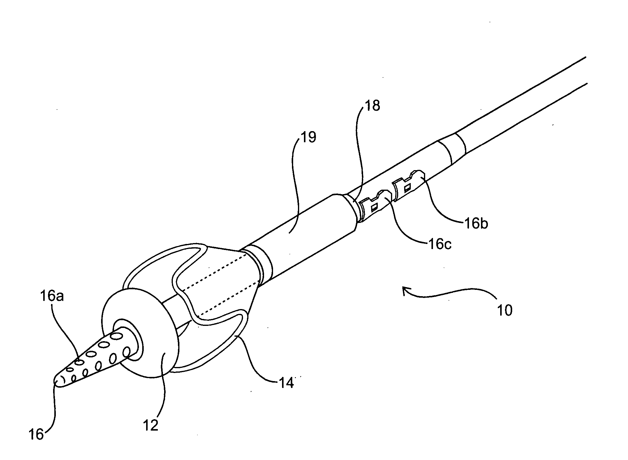
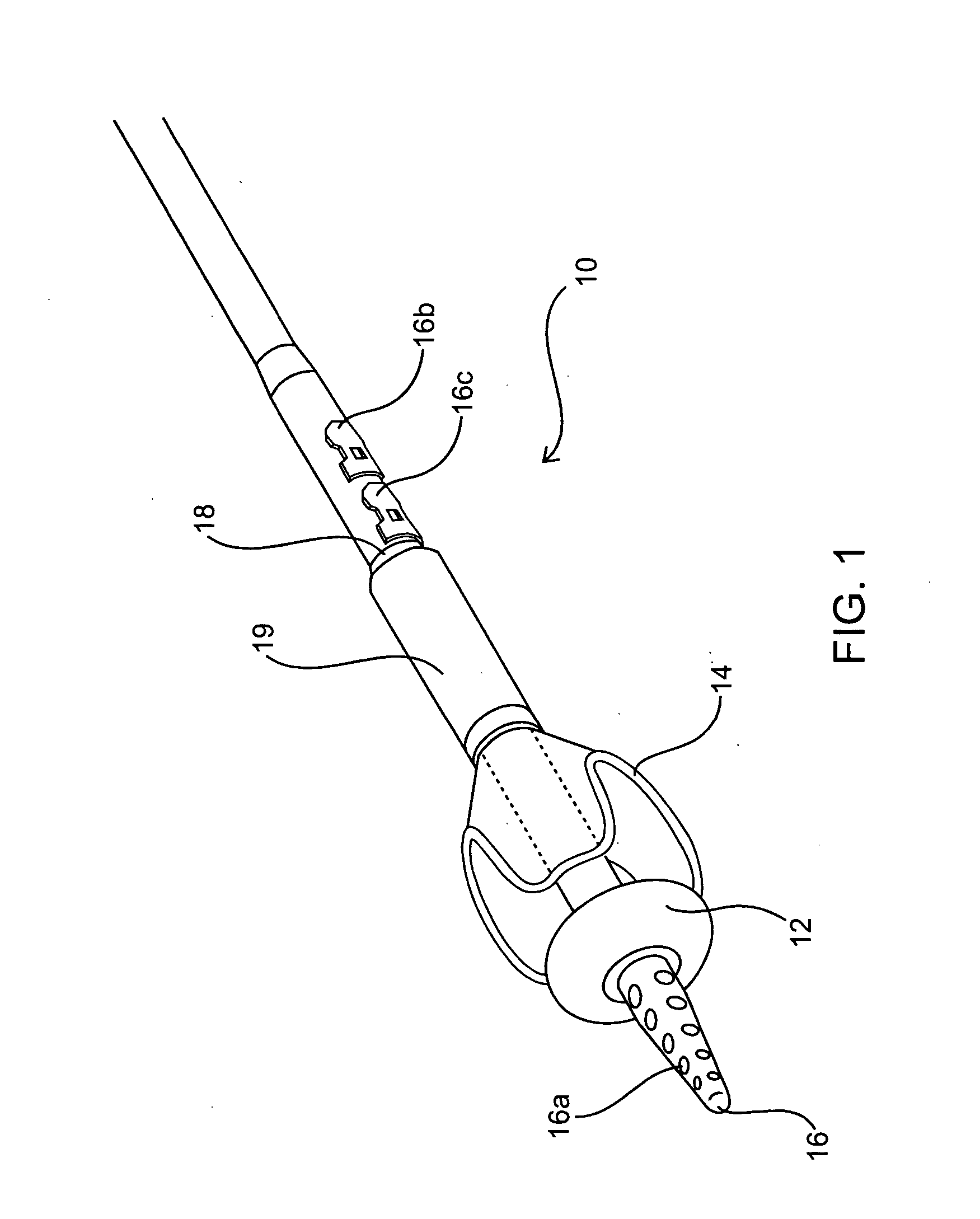
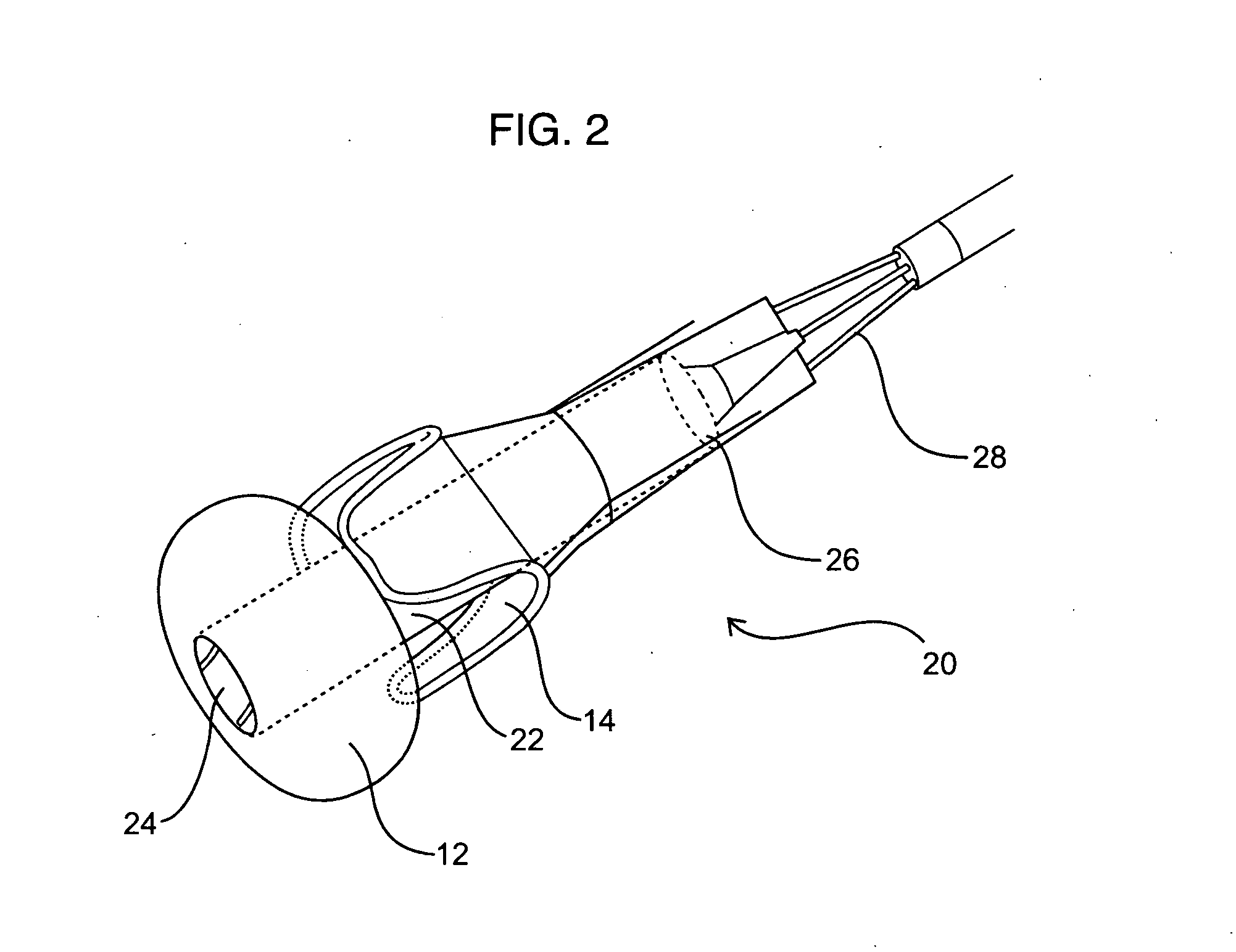
[0016] Devices and methods for their use in percutaneously increasing the aortic valve flow of a stenotic aortic valve are provided. The subject devices include an aortic valve isolation element, a shunt element and an aortic valve flushing element. The aortic valve isolation element is made up of a ventricular side aortic valve occlusion element and a proximal side aortic valve isolation element. The shunt element is made up of a shunt lumen that includes one or more ventricular side blood inflow ports and one or more proximal side valves that provide for one-way exit of blood from the shunt lumen into the aorta. The aortic valve flushing element is made up of a fluid introducing element and a fluid removal element. In practicing the subject methods, a stenotic aortic valve is first isolated. Next, the isolated valve is flushed with a dissolution fluid, e.g., an acidic dissolution fluid, for a period of time sufficient for the aortic valve flow of the treated valve to be increased....


PUM


Abstract

Devices and methods for their use in percutaneously increasing the aortic valve flow of a stenotic aortic valve are provided. The subject devices include an aortic valve isolation element, a shunt element and an aortic valve flushing element. Also provided are systems and kits that include the subject devices and can be employed in practicing the subject methods. The subject devices, methods, systems and kits find use in treating conditions associated with the presence of stenotic aortic valves.

Description

CROSS-REFERENCE TO RELATED APPLICATIONS [0001] This application claims priority (pursuant to 35 U.S.C. § 119 (e)) to the filing date of U.S. Provisional Patent Application Ser. No. 60 / 531,473 filed on Dec. 19, 2003 and to the filing date of U.S. Provisional Patent Application Ser. No. 60 / 488,507 filed on Jul. 17, 2003; the disclosures of which are herein incorporated by reference.INTRODUCTION [0002] 1. Background of the Invention [0003] Aortic valve stenosis refers to a disease condition characterized by a narrowing of the aortic valve. While aortic valve stenosis can results from the presence of a bicuspid valve or rheumatic fever, wear and tear of the aortic valve in the elderly is the most common cause of this condition. This latter condition is known as “senile calcific aortic stenosis.” With aging, protein collagen of the valve leaflets is destroyed, and calcium is deposited on the leaflets. Once valve leaflet mobility is reduced by calcification, turbulence across the valve in...

Claims


Application Information

Patent Timeline
Patent Type & Authority Applications(United States)
IPC IPC(8): A61B17/12A61B17/22A61F2/958A61MA61M29/00A61M29/02
CPCA61B17/12045A61B17/12131A61B17/12136A61B17/22A61B2017/12127A61M2025/1095A61B2017/22067A61B2017/22084A61M25/10A61M2025/1052A61M2025/109A61B2017/22054
Inventor LAIRD, ROBHELKOWSKI, RICK
Owner CORDIS CORP
Why Eureka
Try Eureka