Power generation plant

a power generation plant and power generation technology, applied in the direction of machines/engines, sustainable transportation, mechanical equipment, etc., can solve the problems of secondary machine not being able to reach the possible top process temperature, secondary machine cannot operate normally below, and both types of construction have comparatively poor scaleability of operation, so as to achieve high flexibility in the utilization of waste hea

Inactive Publication Date: 2005-03-17
ALSTOM TECH LTD
View PDF6 Cites 62 Cited by
  • Summary
  • Abstract
  • Description
  • Claims
  • Application Information

AI Technical Summary

Benefits of technology

[0007] It is therefore an aspect of the present invention to specify a power generation plant of the type mentioned at the beginning which avoids the disadvantages of the prior art and in which, in particular, high flexibility in the utilization of the waste heat is provided for.
[0008] An aspect of the invention is therefore to arrange a machine working with a gaseous process fluid and having a physically completely closed fluid cycle as secondary machine. It is in this case well-understood that this process fluid—process gas—does not pass through any phase change during the entire cyclical process of the secondary machine. In the secondary machine, the gaseous process fluid is first of all compressed, then directed on the secondary side through the exhaust-gas heat exchanger of the primary gas turboset, where it absorbs heat, expands and is returned completely for compression, in which case, preferably before and / or during the compression, heat dissipation from the process fluid takes place in a heat sink. The conduction of the process fluid in a closed cycle offers surprising advantages especially for the utilization of the waste heat: firstly, the process fluid can be freely selected in order to obtain, for example, thermodynamic properties of the process fluid which are suitable in an especially effective manner for utilization at low temperatures. Furthermore, the mass flow of the circulating fluid can be changed by adapting the overall pressure level of the secondary process, as a result of which it is possible to react to a, for example, decreasing supply of waste heat at an essentially constant temperature, with an essentially uniform pressure ratio and thus with the secondary machine still at a good efficiency. In other words, it is thus possible, by simply varying the overall pressure level of the secondary process, by supply or discharge of circulating process fluid, to set the mass flow of the latter in such a way that the top process temperature of the secondary machine is close to the exhaust-gas temperature of the primary machine. Thus, in an exemplary operating mode of the power generation plant according to the invention, the cycle charge, thus the overall pressure level of the process, is regulated in such a way that the top process temperature of the secondary machine in steady-state operation is never more than 50° C., preferably 30° C., below the exhaust-gas temperature of the primary machine, and, in particular, this temperature difference, which is necessary in order to provide a temperature gradient driving the heat transfer, is adjusted within a range of 5° C. to 20° C.; in this case, the value which can be achieved also depends on the size of the heat transfer areas available. Furthermore, since no phase change of the process fluid takes place, operation at a low top process temperature is also possible without it being necessary, as described at the beginning, to pay attention to a minimum requisite live steam temperature of a two-phase process. It can readily be understood that superior flexibility in the utilization of the waste heat of a gas turboset is made possible by the invention.

Problems solved by technology

Both types of construction have comparatively poor scaleability of the operation for different supplies of waste heat.
The secondary steam cycle therefore cannot normally be operated below a minimum exhaust-gas temperature of the primary machine.
However, if the supply of waste heat varies, for example on account of an adjustment of the inlet guide row of the primary machine, and the temperature level of the waste heat remains approximately constant, the case will also occur where the secondary machine is no longer able to reach the possible top process temperature.

Method used


Image

  • Power generation plant
  • Power generation plant
  • Power generation plant

Examples


Embodiment Construction

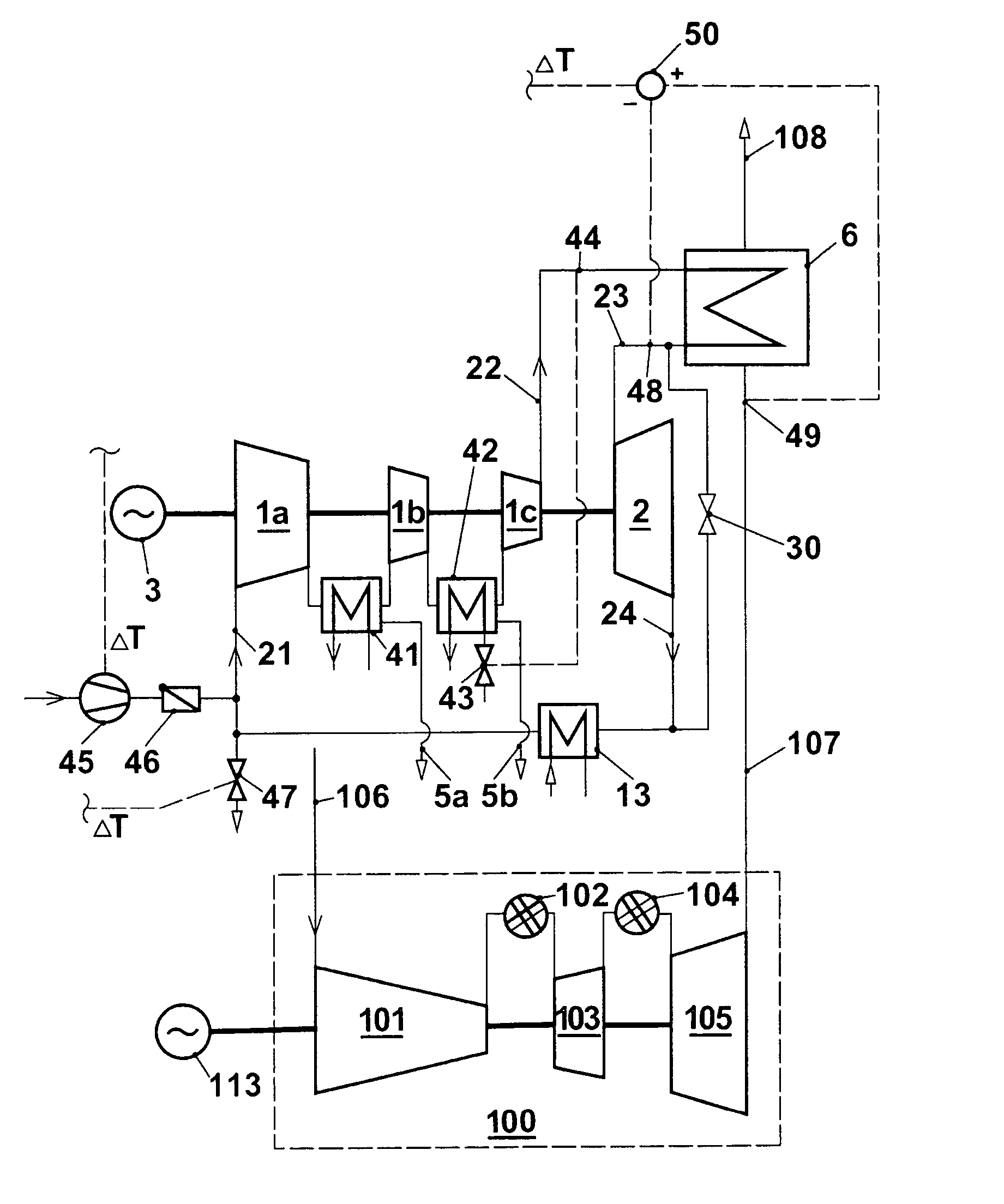
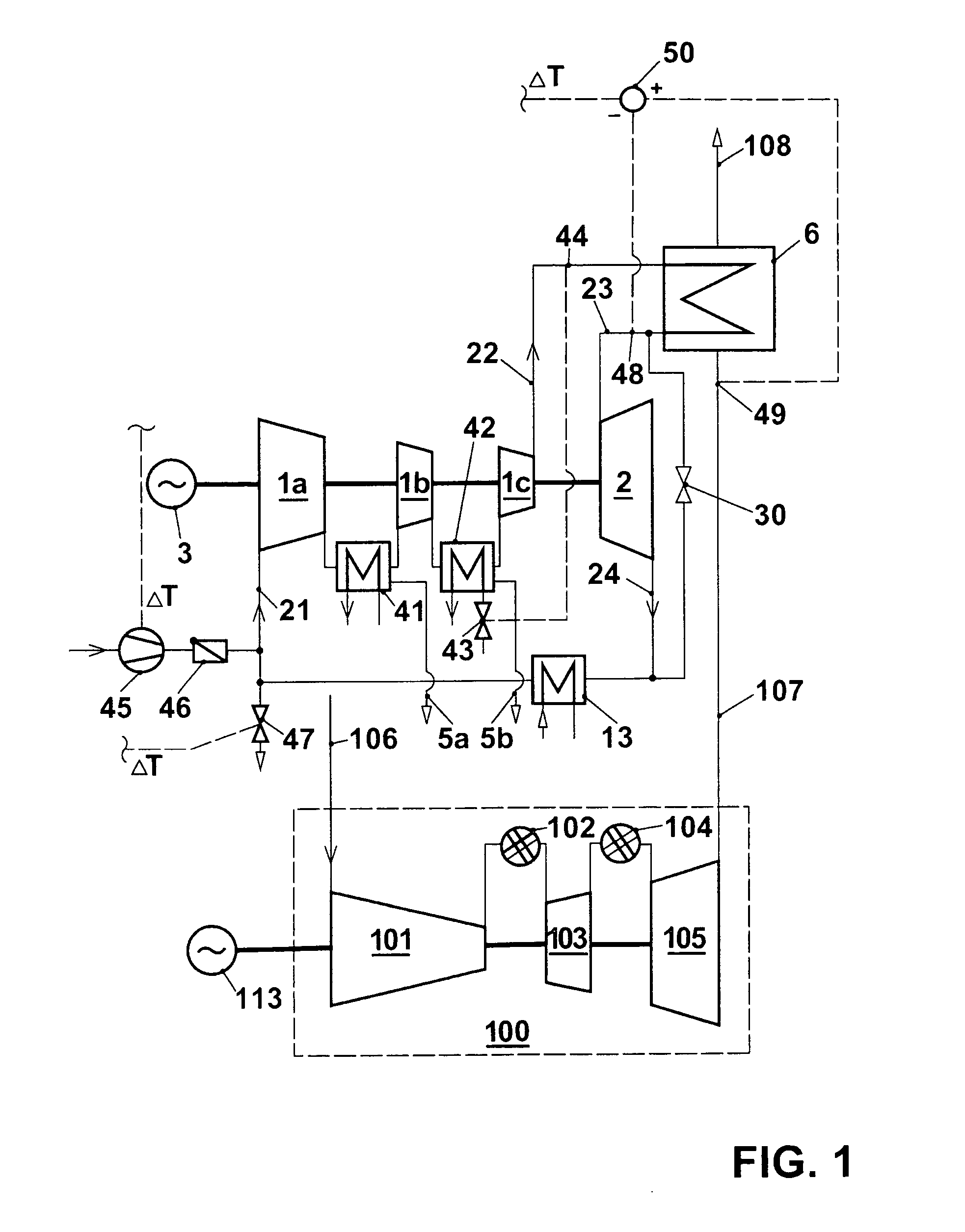
[0017] A power station plant according to the invention is shown in FIG. 1. As primary machine, a gas turboset 100 drives a generator 113. Without constituting a restriction, this gas turboset is one with sequential combustion, as is well known from EP 620 362 and numerous publications based thereon. Without going into details, its basic function is briefly explained. A compressor 101 and two turbines 103 and 105 are arranged on a common shaft. The compressor 101 draws in an air quantity 106 from the environment. Fuel is admixed with the compressed air in the first combustion chamber 102 and burned there. The flue gas is partly expanded in the first turbine 103, for example at a pressure ratio of 2. The flue gas, which still has a high residual oxygen content of typically over 15%, flows into a second combustion chamber 104, where further fuel is burned. This reheated flue gas is expanded in the second turbine 105 approximately at ambient pressure—apart from pressure losses of the e...


PUM


Abstract

In a power generation plant, for example a power station plant for the generation of electricity, a secondary machine (1a, 1b, 1c, 2) is connected downstream of an open-cycle gas turboset (100) for the utilization of the waste heat of the exhaust gases (107). The secondary machine is a machine working in a closed cycle with a gaseous process fluid, for example a closed-cycle gas turboset having a compressor (1a, 1b, 1c), a device for heating the compressed gas (6) which utilize the waste heat of the exhaust gas (107) of the primary gas turboset (100), a turbine (2) and at least one heat sink (13). In one embodiment, intercoolers (41, 42) are arranged during the compression process. A variable cycle charge of the secondary machine permits superior flexibility in the utilization of greatly varying supplies of waste heat available.

Description

[0001] This application is a Continuation of, and claims priority under 35 U.S.C. § 120 to, International application number PCT / EP03 / 50054, filed 11 Mar. 2003, and claims priority under 35 U.S.C. § 119 to Swiss application number 2002 0444 / 02, filed 14 Mar. 2002, the entireties of both of which are incorporated by reference herein.BACKGROUND OF THE INVENTION [0002] 1. Field of the Invention [0003] The present invention relates to a power generation plant, in particular a power station plant. It also relates to a method of operating a power station plant. [0004] 2. Brief Description of the Related Art [0005] Power station plants in which a secondary machine is connected downstream of a gas turboset acting as primary machine in order to utilize the waste heat are already best known per se as combined cycle plants. In the most common embodiment, a heat-recovery steam generator is arranged in the exhaust-gas duct of a gas turboset, a steam quantity which is used to drive a steam turbin...

Claims


Application Information

Patent Timeline
Patent Type & Authority Applications(United States)
IPC IPC(8): F02C1/10F02C6/18
CPCF02C1/105Y02T50/672F02C6/18Y02T50/60
Inventor FRUTSCHI, HANS ULRICHDITTMANN, ROLF
Owner ALSTOM TECH LTD
Why Eureka
Try Eureka