Pneumatic closed-looped antilock pressure modulating device for pneumatic brake systems

a closed-looped, anti-locking technology, applied in the direction of brake safety systems, vehicle components, braking systems, etc., can solve the problems of acm not being able to prevent the wheels from locking, acm being subject to contaminants, and malfunctioning,

Inactive Publication Date: 2005-03-17
WASHINGTON WILLIAM E
View PDF1 Cites 15 Cited by
  • Summary
  • Abstract
  • Description
  • Claims
  • Application Information

AI Technical Summary

Benefits of technology

[0035] Another object of the present invention, and an improvement over all quick release valves, is to provide a valve of the type whose functions eliminate the degenerative effect created by the front-to-back braking time differential, as the ideal braking situation is to have balance throughout the plurality of brake actuators.
[0037] Yet another object is to provide a valve whose mechanisms provide for consistent performance, maintainability and reliability over a relatively long lifetime.
[0038] Still another object is to provide a valve whose exhaust / relief function does not cause sluggish release of fluid volume in plurality brake actuator designs but works mechanically as an integral part of the brake system design to insure quick release of fluid pressure volume between opposing actuators per axle in all vehicle axle configurations and is an improvement over the trailer brake release valve.
[0039] Still another object of the present invention is to provide a single valve whose performance exceeds those of the aforesaid patents with the improvements necessary to prevent the consequences cited of same said patents.

Problems solved by technology

They cannot prevent wheel lockup.
Thus the ACM cannot prevent the wheels from locking.
The ACM is subject to contaminants and malfunction because of this.
Venting of the fluid pressure is an “after-the-fact” event; the patent is in conflict in that it claims to prevent brakes from locking up and in fact vents air after they lockup.
The recovery time of fluid pressure buildup causes abrupt shock waves in the pneumatic portion of the brake system.
The shock waves increase the applied pressure to induce excessive variable pressures.
This approach is nothing more than a “bleeder valve” and it creates multiple problems for manufacturers and maintenance personnel.
Therein lies the problem for electronic antilock brake systems.
Electronic antilock systems are digital and must be programmed, thereby processing a limited amount of data.
A digital device cannot process the infinite amount of analog data that causes the various types of wheel lockup.
Also the thermodynamically induced eccentricities on the drum contact surface circumference and the warping on the rotor surfaces cause discontinuities during the drum-lining or rotor-lining dynamic interface, thereby causing interference with consistency in the electronic antilock venting cycle.
Electronic antilock brake systems cannot cycle fast enough to achieve the desired affects, thereby causing vehicle instability during the braking cycle.
Venting of the air results in the momentary decrease in the fluid pressure within the brake system.
Also during this cycle, the brakes are momentarily not applied, thereby causing the vehicle to increase its stopping distance.
The ECU and ACM approach does nothing to prevent the incidence of single-wheel lock-up that is the cause of jackknifing and the loss of vehicle stability.
The industry has reported that drivers have a difficult time viewing the external warning light from the cab.
Still others have reported that one does not know if the light is to be off or on.
The truck, trailer and bus ECU / ACM are equally vulnerable.
The State of Georgia encountered a major problem with the school buses that were equipped with electronic antilock brake systems.
The ECU components were programmed with incorrect algorithms that caused delays in the delivery of fluid pressure to the air chambers.
The malfunction warning lights were unable to detect the problems with the computer programming.
Additionally, the emergency brake portion of the air chambers will engage, immobilizing the vehicle.
The device described by Vorech employs the use of a spring acting upon a diaphragm in such a manner that a pressure differential exists across the diaphragm, and this feature results in somewhat slower application of the front brakes as compared with the rear brakes and causing a lesser energization of the front brakes than that of the rear brakes.
This device causes a purposeful time and application differential with the negative effect of unbalanced front-to-back braking and uneven front-to-back wear on brake components, with the back brakes wearing prematurely to the front brakes.
Cannella's device also lacks the design to address the fluid pressure wave front that so readily travels through the relay valve crossing to and from opposing brake actuators and causing single wheel lock-up.
It was found that as the piston is acted upon by fluid pressure, said piston deforming the elongated member and having the result of energization of said member, upon release of the fluid pressure the piston becomes a projective traveling into the second lower chamber causing physical damage to the dividing resilient member, the result being contamination of the upper chamber and inconsistent equalizing of pressure and an inability to absorb shock.
Another result being the fluid pressure volume would cause the damaged divider member to enter the outlet port, clogging the conduit and preventing fluid pressure from flowing to the brake actuator.
These consequences are entirely due to the piston's lack of an established point of rest.
As the initial shock occurs in the quick release valve and not in the apparatus, the apparatus cannot absorb the shock and the ideal braking effectiveness is diminished.

Method used


Image

  • Pneumatic closed-looped antilock pressure modulating device for pneumatic brake systems
  • Pneumatic closed-looped antilock pressure modulating device for pneumatic brake systems
  • Pneumatic closed-looped antilock pressure modulating device for pneumatic brake systems

Examples


Embodiment Construction

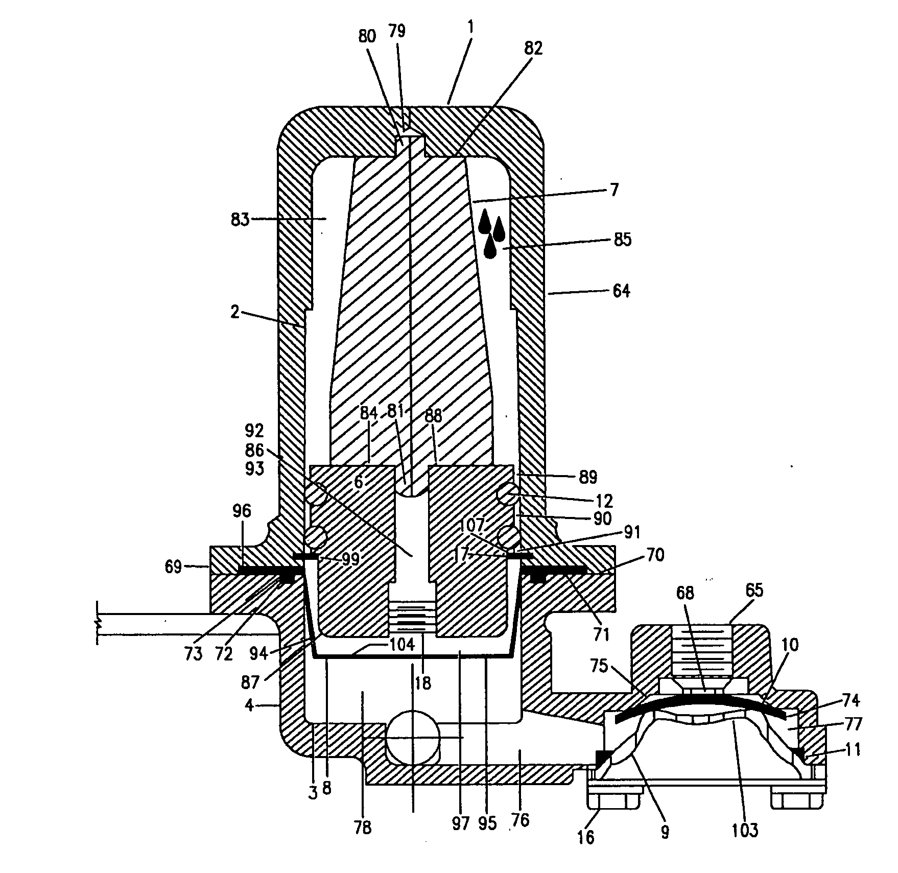
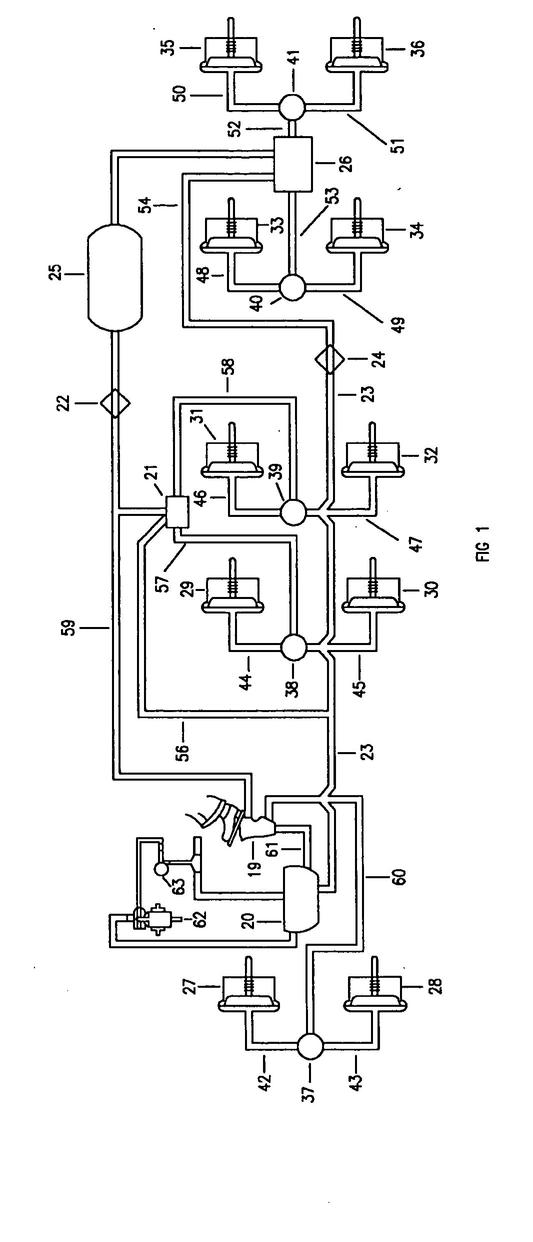
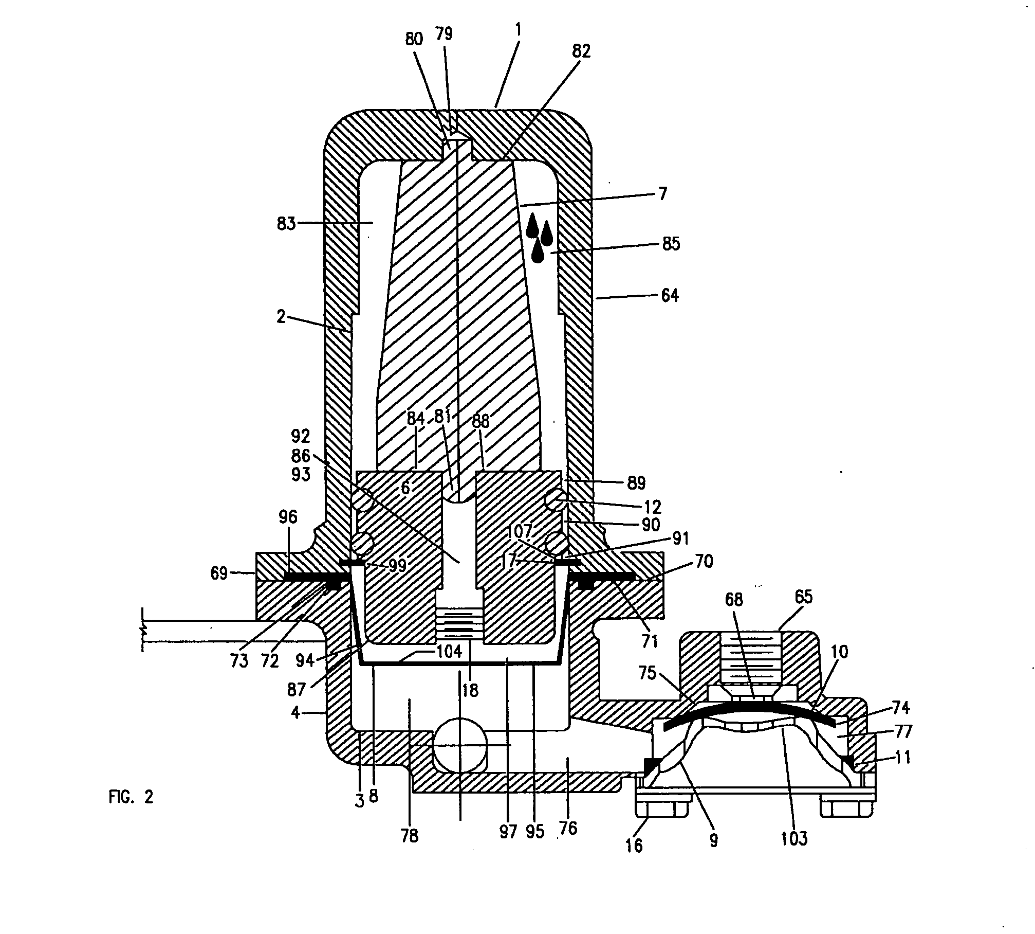
[0051] Referring more particularly to FIG. 1, the novel differential pressure regulator quick release valves of the present invention are illustrated therein in connection with a pneumatic fluid pressure vehicle braking system. Said braking system includes; a truck reservoir 20 supplied by a conventional compressor 62, a conventional governor 63 employed for controlling the operation of the compressor 62 in accordance with the pressure of the air within the reservoir 20, a reservoir 25 for the trailer, a treadle valve 19, opposing brake actuator chambers 27 and 28 (FIG. 9), 29 and 30, 31 and 32, 33 and 24, 35 and 36, a conventional relay valve 21, an emergency relay valve 26, glad hands 22 and 24 connecting the trailer / truck air brake systems. Also shown in FIG. 1 are the conduits 60, 57, 58, 52 and 53, whose purpose is to direct fluid pressure to the invention 37, 38, 39, 40, and 41 of the patent, and are interposed respectively between opposing brake actuators 27-36, and connected...


PUM


Abstract

This invention relates to a pneumatic closed-looped antilock pressure device in a pneumatic brake system for a truck tractors, semi-trailer and buses, and a differential pressure regulator for pneumatic brake system as it pertains to pneumatic brake systems for semi-trailers, buses, trucks, and trucks / semi-trailers, singular and in multiple combinations in automotive air brake installations; and more particularly to a pressure modulating device that employs a diaphragm, piston and elastomeric member with pneumatic antilock brake system functions, a means for modulating pneumatic signals, a means for oscillating pneumatic signals and a means relieve pressure internally, therewith sensing pneumatic shock wave signals, and dampening shock waves, and automatically adjusting brake actuation forces and the degree of angular rotation of the wheels in a closed-looped system without venting pressure to the atmosphere.

Description

BACKGROUND OF THE INVENTION I [0001] This invention is directed to a pneumatic brake system whose pressure reduction means is internal, being closed-looped and compensating for the multi-phase pressure differentials by sensing pneumatic signals that are inherent to all fluid based friction-type braking systems. A purpose of this invention is to show that the pneumatic signal sensing means and pneumatic signal output means of the invention is continuous, thereby the same automatically and continually adjusts the angular rotation of the wheels and these means are an improvement over a control module for a brake system for trucks and semi-trailers, and other electronic control modules. Another purpose of the invention is to demonstrate a novel approach to sensing infinite pneumatic signals within limits in a closed-looped pneumatic antilock braking system that is an improvement over all electronic antilock brake systems, and is not obvious to those who are skilled in the art of brake m...

Claims


Application Information

Patent Timeline
Patent Type & Authority Applications(United States)
IPC IPC(8): B60T8/176B60T15/22B60T17/22
CPCB60T8/176B60T17/22B60T15/22
Inventor WASHINGTON, WILLIAM E.
Owner WASHINGTON WILLIAM E
Why Eureka
Try Eureka