
Geometrically aligning a stator and a base plate for a spindle motor

a stator and spindle motor technology, applied in the field of spindle motors, can solve the problems of limiting the density and overall performance of the data track of the disc drive system, the alignment of the stator and the magnet, and the cost and difficulty of the alignment of the stator and the base plate in both the axial and radial directions, so as to reduce the vibration and acoustics of the stator, and improve the stiffness of the stator

Inactive Publication Date: 2005-03-17
SEAGATE TECH LLC
View PDF5 Cites 17 Cited by
  • Summary
  • Abstract
  • Description
  • Claims
  • Application Information

AI Technical Summary

Benefits of technology

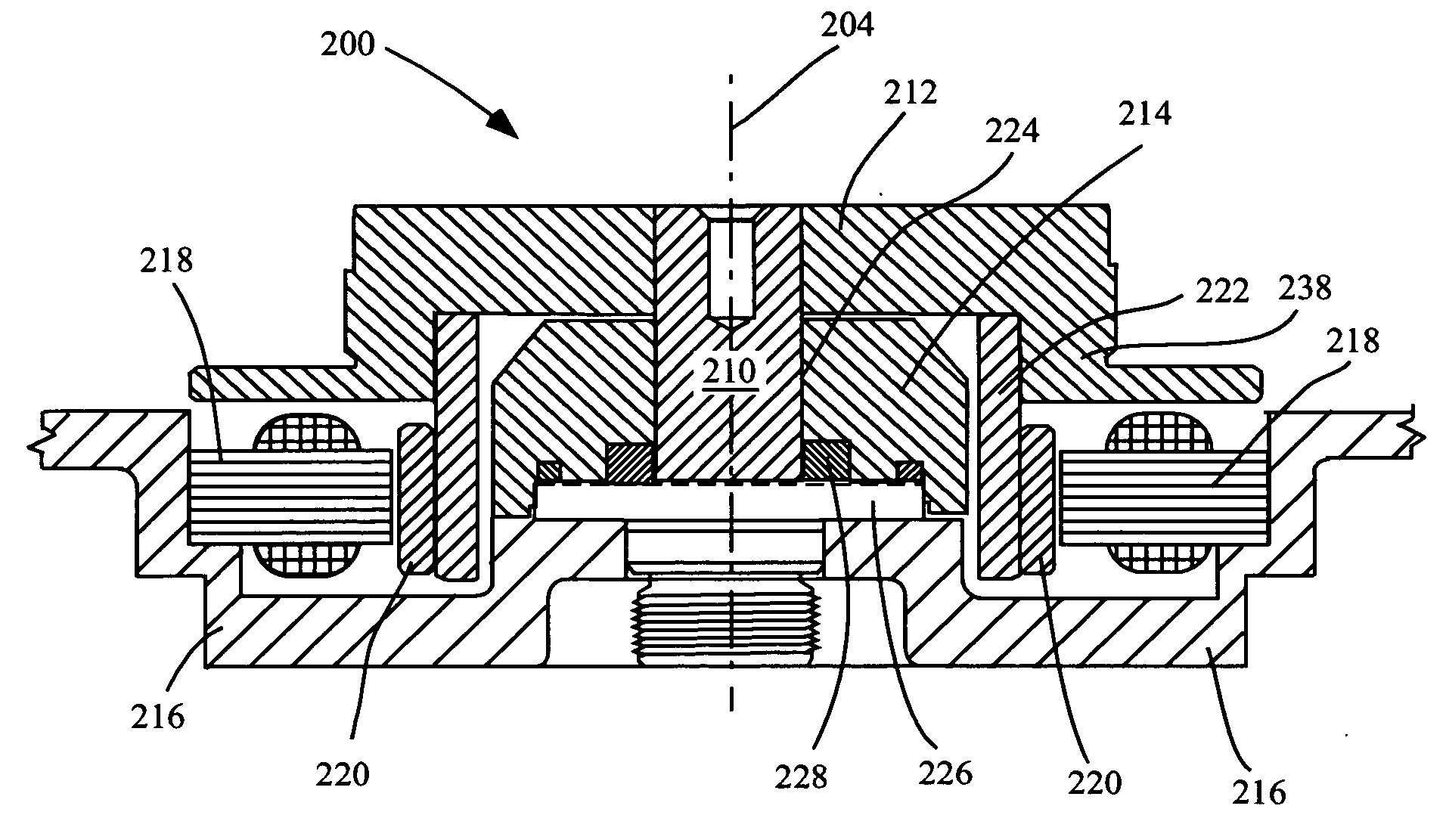
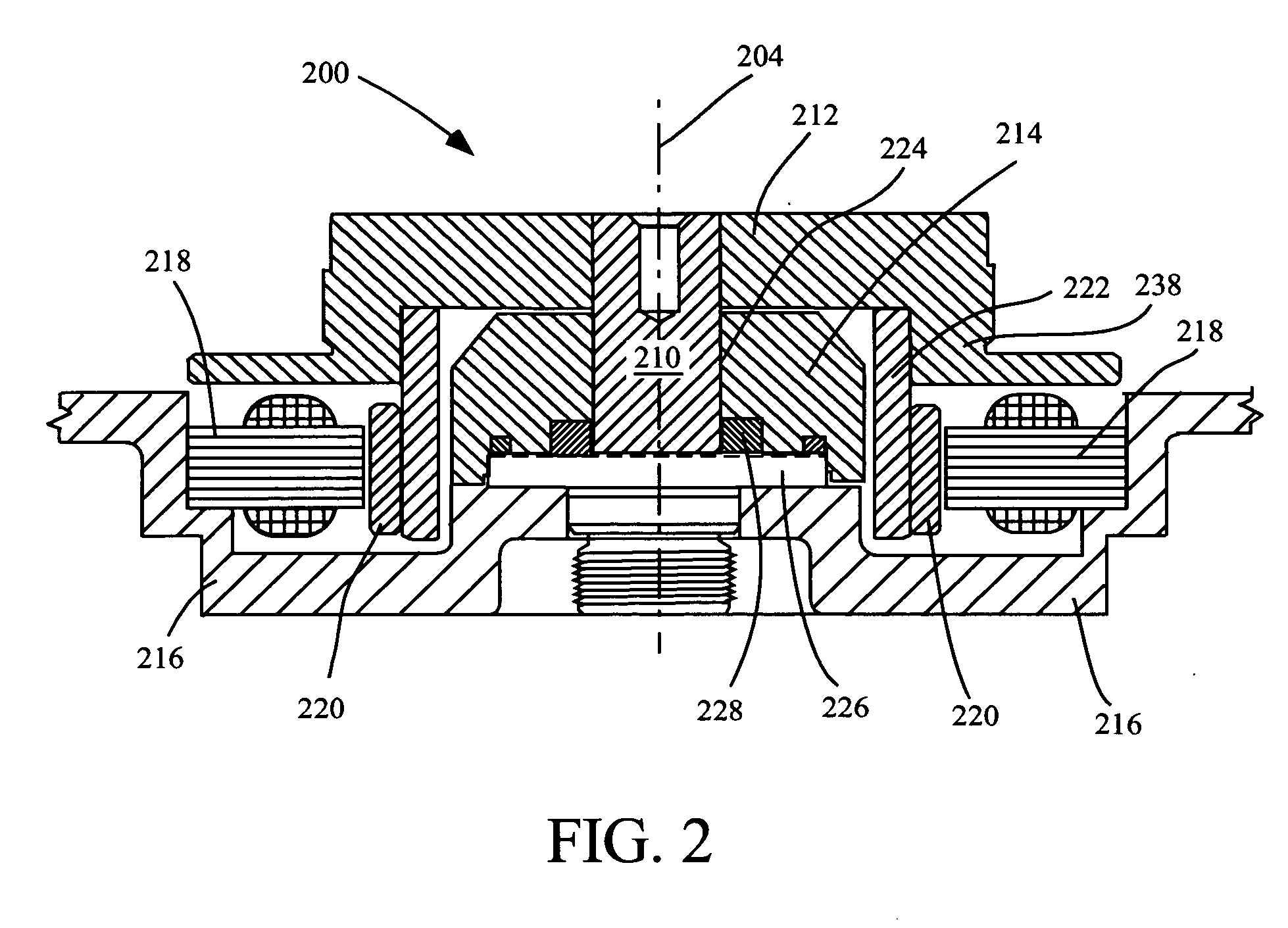
[0010] A stator and a base plate are provided having an interface alignment that consistently meets design specifications such that motor performance is maintained. In an embodiment, desired and accurate stator parallelism, z-height and concentricity are provided. Further, in an embodiment, the present invention improves stator stiffness, and reduces stator vibration and acoustics. The present invention may be utilized with low profile disc drive memory systems.
[0011] Precise machining of a small corner interface of the base plate wherein a stator is typically seated and aligned with the base plate is made unnecessary. In component stamping processes for forming a base, component machining costs are reduced. Wear and tear to machining systems, and machining process cycle times are reduced. Further, motor performance and space management requirements can be more easily met.
[0013] The stator bottom layer laminations seat on the flat base machined surface, avoiding a base plate corner radius. The bottom layer laminations of the stator bottom surface are used to set the stator z-height and parallelism with respect to the machining plane datum. A small separation can be maintained between the base plate inside diameter (ID) and the outside diameter (OD) of the stator top layer laminations, providing improved radial alignment. The outer diameter of the top layers of the stator is used to set the concentricity of the stator with respect to the rotating axis of the spindle motor. More specifically, the bottom layers of the stator laminations OD is formed less than the base ID less two multiplied by the base corner radius. Further, the total stack height of the bottom layers of the stator laminations is formed greater than the base corner radius.

Problems solved by technology

For example, a CF card type I form factor requires a disc drive having a 3.3 mm thickness but such disc drive is not yet on the market.
Misalignment and mispositioning between data tracks and the read / write transducer can limit the data track density and overall performance of the disc drive system.
Alignment of the magnet and stator, and alignment of the stator and base plate, in both the axial and radial direction is expensive and difficult during volume production of disc drive motors due to tolerances incurred in producing the magnet, stator and base plate parts.
In manufacturing a base plate for a disc drive having a thin dimension, aluminum base casting becomes ever more difficult and it has become a trend to utilize a stamping technology to reduce manufacturing costs.
However, accurately machining a properly aligned base plate and stator interface is problematic, in part due to the small dimensions.
Further, added difficulties arise in machining a stamped steel base including increased cutter wear and a longer process cycle time, as compared to machining an aluminum base.

Method used


Image

  • Geometrically aligning a stator and a base plate for a spindle motor
  • Geometrically aligning a stator and a base plate for a spindle motor
  • Geometrically aligning a stator and a base plate for a spindle motor

Examples


Embodiment Construction

[0024] Exemplary embodiments are described with reference to specific configurations. Those of ordinary skill in the art will appreciate that various changes and modifications can be made while remaining within the scope of the appended claims. Additionally, well-known elements, devices, components, methods, process steps and the like may not be set forth in detail in order to avoid obscuring the invention.

[0025] A system and method is described herein for consistently providing desired alignment of a stator and a base plate such that motor performance is maintained and precise machining of a stator and base plate small corner interface is unnecessary. In an embodiment, desired and accurate parallelism, z-height and concentricity is provided.

[0026] It is to be appreciated that features of the discussion and claims may be utilized with disc drives, low profile disc drive memory systems, spindle motors, ball bearing designs, various fluid dynamic bearing designs including hydrodynam...


PUM


Abstract

Stator and base plate interface alignment is provided for a spindle motor, meeting design specifications such that motor performance is maintained. A portion of a surface of the stator is separated from the base plate. Accurate stator z-height, parallelism and concentricity are provided for use with a low profile disc drive memory system. In an aspect, laminations are formed about a stator and the bottom layer laminations are formed with a smaller diameter than the top layer laminations. The stator bottom layer laminations seat on a flat base plate machined surface, avoiding a base plate corner radius. Precise machining of a small corner interface of the base plate where a stator is typically seated and aligned with the base plate is made unnecessary. Component machining costs, wear and tear to machining systems, and machining process cycle times are reduced.

Description

CROSS REFERENCE TO RELATED APPLICATION [0001] [0001] This application is based on a provisional application Ser. No. 60 / 503,552, filed Sep. 16, 2003, attorney docket number STL3449.01, entitled Motor Stator Design With Laminations Of Different Size, and assigned to the Assignee of this application and incorporated herein by reference.FIELD OF THE INVENTION [0002] The invention relates generally to spindle motors, and more particularly to seating a stator with a base plate, aligned with accurate z-height, parallelism and concentricity for use with a low profile disc drive memory system. BACKGROUND OF THE INVENTION [0003] Disc drive memory systems have realized intensified demands because of new environments for usage, miniaturization and increased performance needs. Besides traditional computing environments, including PCs, network servers and workstations, disc drive memory systems are currently used by devices including digital cameras, digital video recorders, laser printers, phot...

Claims


Application Information

Patent Timeline
IPC IPC(8): H02K1/14H02K1/18H02K5/06H02K21/16
CPCH02K1/146H02K21/16H02K5/06H02K1/185
Inventor XU, MOCHOO, VICTOR C.HONG, YIRENLIM, POHLYE
Owner SEAGATE TECH LLC
Learn More