Method of detecting attracting force between substrates, and near-field exposure method and apparatus

a technology of attraction force and substrate, which is applied in the direction of photomechanical equipment, instruments, printing, etc., can solve the problems of mask breakage, difficult for projection exposure equipment to produce a pattern of 0.10 m or less, and difficult to achieve exposure, so as to prevent the mask from breaking, the effect of yield and throughput for wafers and glass substrates

Inactive Publication Date: 2005-03-17
CANON KK
View PDF6 Cites 16 Cited by
  • Summary
  • Abstract
  • Description
  • Claims
  • Application Information

AI Technical Summary

Benefits of technology

[0023] In accordance with the present invention, the attraction force between substrates can be detected, this being particularly effective to prevent breakage of an exposure mask during an exposure process. Thus, the present invention can provide a near-field exposure method and apparatus by which the yield and throughput for wafers and glass substrates, for example, can be improved.
[0024] Particularly, when the attracting force detecting means of the present invention is applied to a near-field exposure method and apparatus and if, at the separation of the exposure mask and the resist, the pressure at start of tearing is lower than a preset value, or if a largest angular change is larger than a preset value, use of the exposure mask can be interrupted. This effectively avoids breakage of the exposure mask during operation of the exposure apparatus. As a result of this, there is no possibility that fragments of the exposure mask are scattered over the resist or inside the exposure apparatus, and the yield of wafers or glass substrates to be produced can be increased. Furthermore, the necessity of complicated works for removing fragments inside the exposure apparatus, caused by breakage of the exposure mask, can be removed or reduced, and the throughput of the apparatus can also be improved.

Problems solved by technology

Even if an excimer laser is used, it is difficult for a projection exposure apparatus to produce a pattern of 0.10 μm or less.
Additionally, even if there is a light source having a shorter wavelength, the optical material (i.e., lens glass material) used in a projection optical system could not transmit such short wavelength, and, because the pattern could not be projected on an object to be exposed, the exposure could not be accomplished.
Also, since the exposure mask used in this method is a mask of elastic material so that it can follow the substrate, when the exposure mask is separated or torn from the resist, a force might be applied to the exposure mask and, in some cases, it is possible that the mask is broken due to this attraction force.
In case the exposure mask is broken during the exposure process, it results in faults in a wafer or glass substrate to be produced and, in turn, it causes a decrease of yield.
First, when the exposure mask is broken, fragments of the exposure mask are scattered over the resist.
If foreign particles such as mask fragments are present on the resist, it leads to a cause for adhesion of foreign particles that interfere with subsequent exposure process and other treatments.
It causes shortened operation time of the apparatus and decreased throughput of it.
Second, even after breakage of the exposure mask, the broken exposure mask may be moved to a subsequent exposure position for the resist, such that fragments of the exposure mask may be scattered over theses portions of the resist.
It leads to a cause for adhesion of foreign particles that interfere with subsequent exposure process and other treatments to be made to the object to be processed such as a substrate.

Method used


Image

  • Method of detecting attracting force between substrates, and near-field exposure method and apparatus
  • Method of detecting attracting force between substrates, and near-field exposure method and apparatus
  • Method of detecting attracting force between substrates, and near-field exposure method and apparatus

Examples


Embodiment Construction

[0036] Preferred embodiments of the present invention will now be described with reference to the attached drawings.

[0037] First, an embodiment of detecting means for detecting an attraction force acting between an exposure mask and an object to be exposed, in accordance with the present invention will be described.

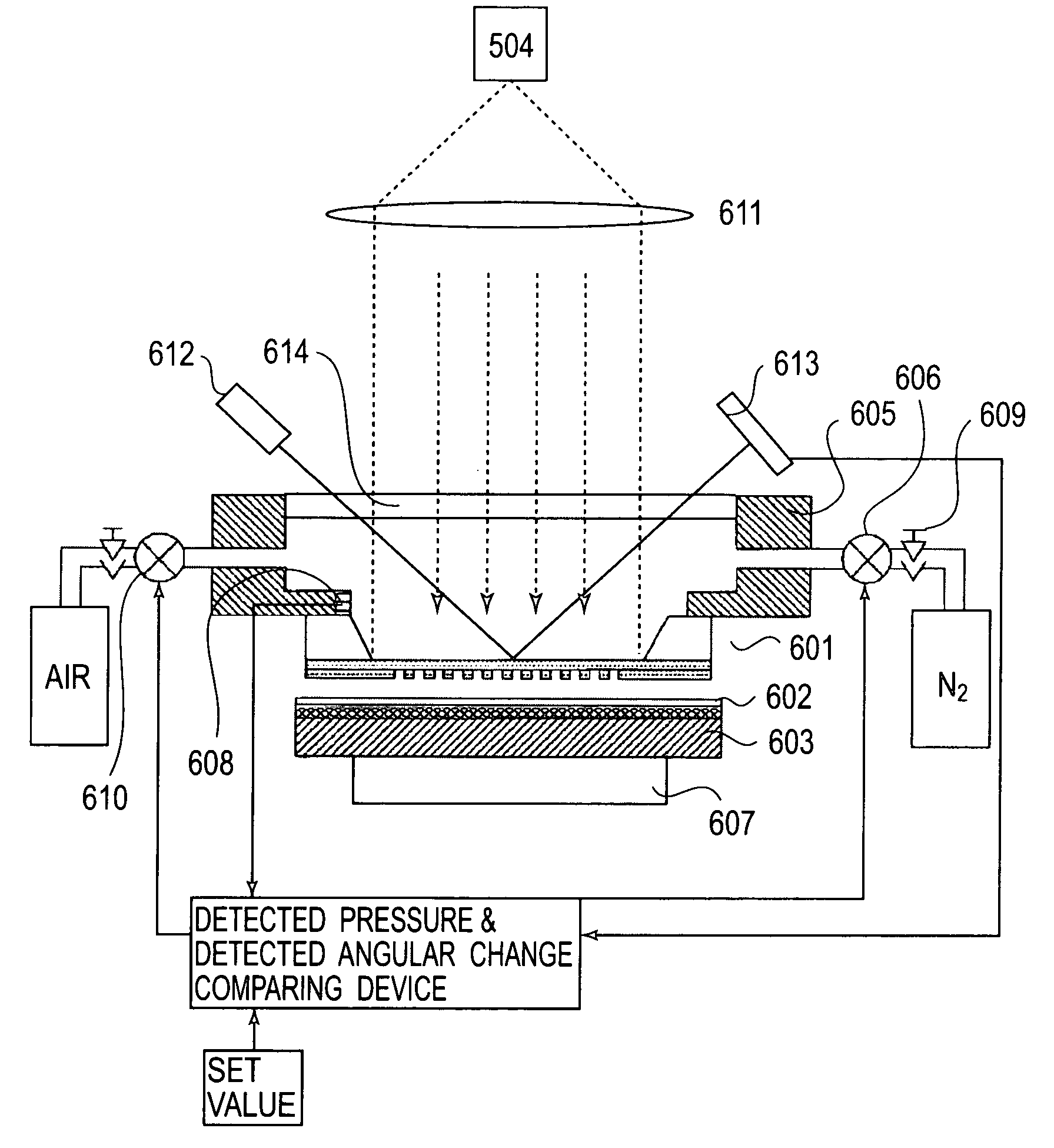
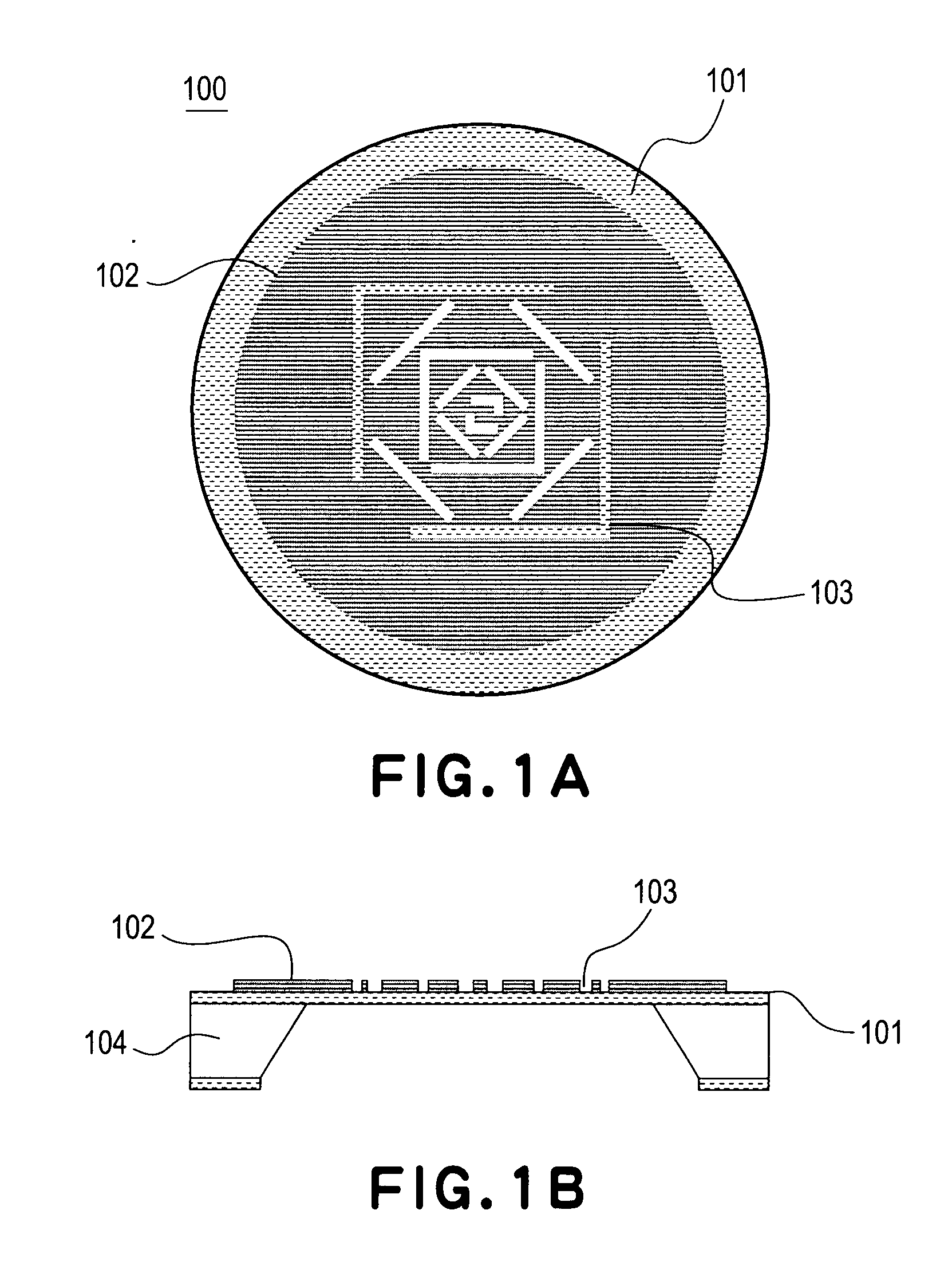
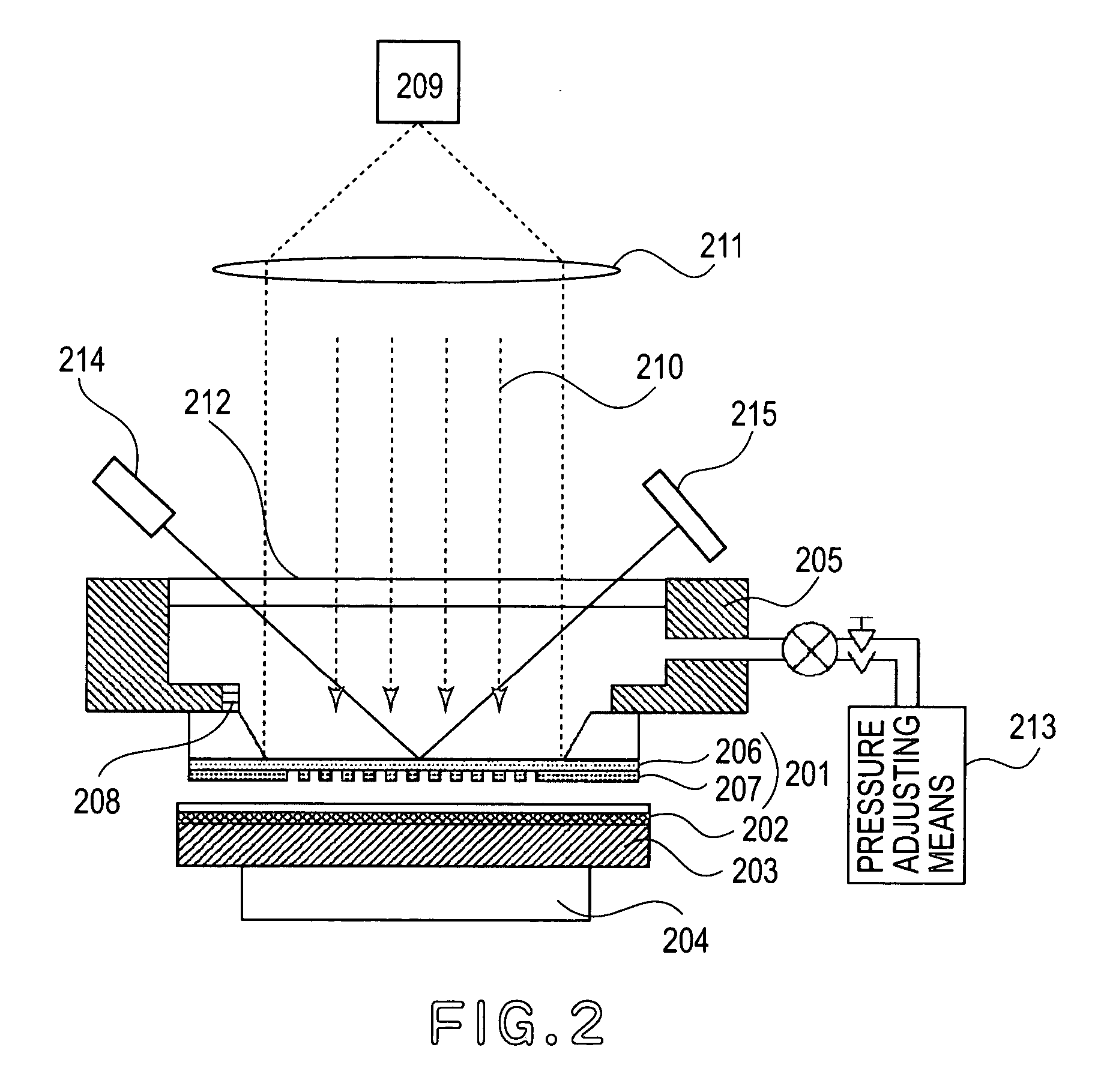
[0038]FIGS. 1A and 1B illustrate the structure of an exposure mask which is the subject of breakage prediction to be performed in accordance with a breakage predicting method of the present invention. FIG. 2 shows the structure of an exposure apparatus arranged to predict breakage of an exposure mask in accordance with the breakage predicting method of the present invention.

[0039] Referring to FIGS. 1A and 1B, an exposure mask 100 of the present invention will be explained.

[0040]FIGS. 1A and 1B shows an exposure mask which is used in the exposure apparatus shown in FIG. 2, wherein FIG. 1A illustrates the front face side of the mask, and FIG. 1B is a sectional view the...


PUM

PropertyMeasurementUnit
sizeaaaaaaaaaa
distanceaaaaaaaaaa
thicknessaaaaaaaaaa

Abstract

Disclosed is a method of detecting an attraction force between substrates, and a near-field exposure method and apparatus, wherein, in the attraction force detecting method, an elastically deformable first substrate is intimately contacted to a second substrate which is not elastically deformable as compared with the first substrate and, when the first and second substrates so contacted are separated from each other, an attraction force acting between the first and second substrates is detected. Specifically, the includes at least one of (i) a step for detecting an attraction force acting between the first and second substrates on the basis of a difference between (a) a physical quantity necessary for intimately contacting the first substrate to the second substrate and (b) a physical quantity necessary for separating the first substrate from the second substrate, and (ii) a step of detecting an attraction force acting between the first and second substrates on the basis of an amount of deformation of the first substrate relative to the second substrate.

Description

FIELD OF THE INVENTION AND RELATED ART [0001] This invention relates to a method of detecting an attraction force between substrates and to a near-field exposure method and a near-field exposure apparatus. More particularly, the invention concerns near-field exposure method and apparatus which is particularly effective to prevent breakage of an exposure mask in a manufacturing process of integrated circuits or liquid crystal displays (LCD), for example. [0002] Because of recent needs for reduction in size and thickness of electronic instruments, miniaturization of semiconductor devices to be mounted in the electronic instruments has been required more and more. [0003] For example, as regards the design rule for a pattern of a mask or reticle, a line-and-space (L&S) pattern of 130 nm is going to be produced through mass-production, and it will become much smaller soon. Generally, projection exposure apparatuses used recently prevalently have an illumination optical system for illumin...

Claims


Application Information

Patent Timeline
Patent Type & Authority Applications(United States)
IPC IPC(8): G01B11/00B81B3/00G03F7/20H01L21/027
CPCB82Y10/00G03F7/7035G03F7/70325G03F1/14G03F1/50
Inventor INAO, YASUHISAYAMADA, TOMOHIRO
Owner CANON KK
Why Eureka
Try Eureka