Integrated optics polarization beam splitter using form birefringence

a technology of integrated optics and polarization beams, applied in the field of integrated optics polarization beam splitters using form birefringence, can solve the problems of affecting performance, cost and yield, scattering loss, and the inability to deposit most anisotropic materials, and achieves a substantial difference in propagation constants

Active Publication Date: 2005-03-17
INFINERA CORP
View PDF18 Cites 38 Cited by
  • Summary
  • Abstract
  • Description
  • Claims
  • Application Information

AI Technical Summary

Benefits of technology

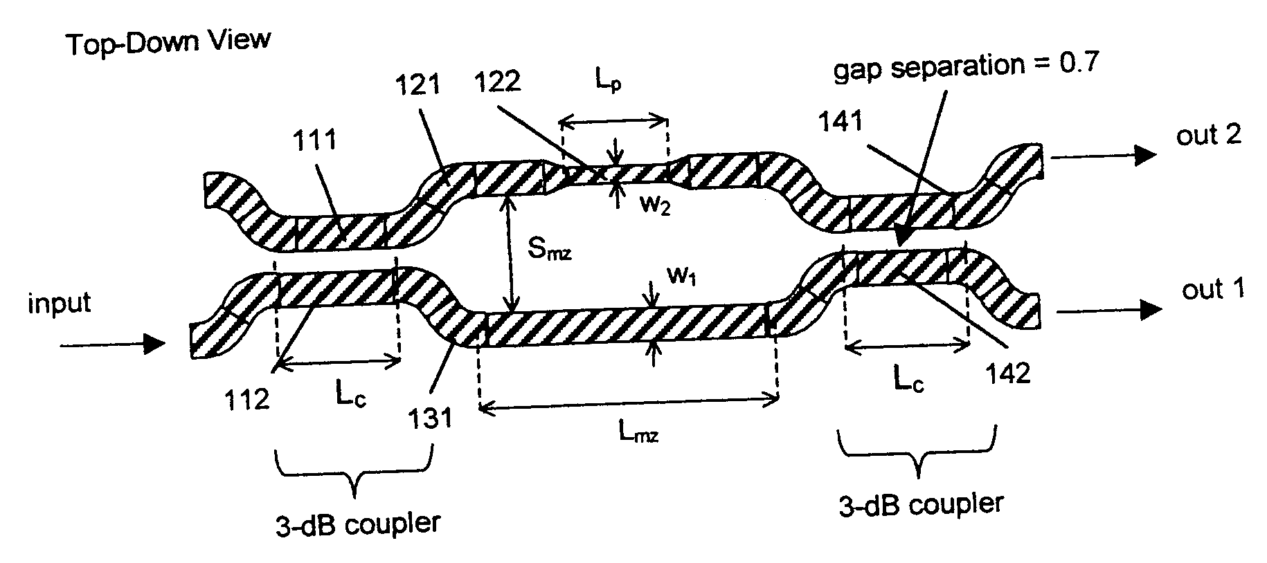
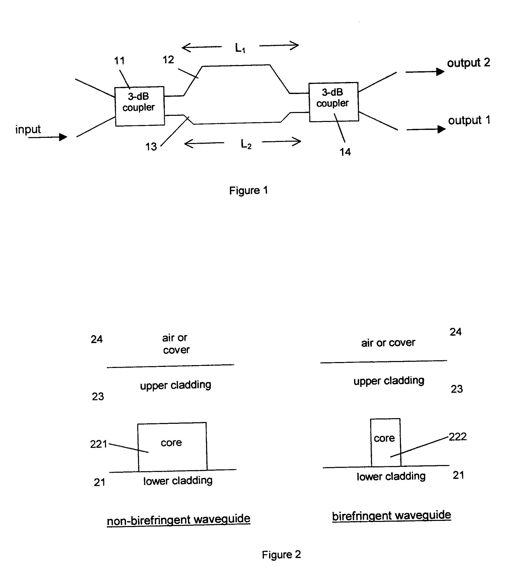
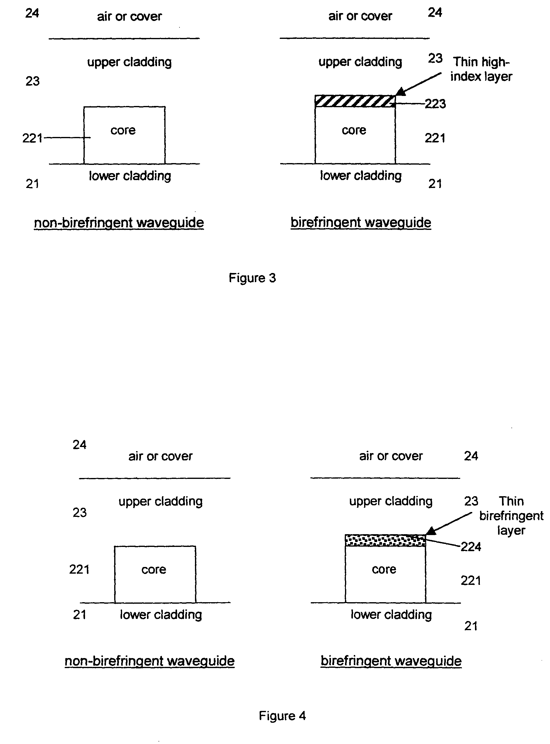
In any polarization splitter design based on a Mach-Zehnder configuration, one must be able to design and fabricate waveguides that have substantially different propagation constants for the TE and TM modes. The term “birefringent” is used to describe the condition where the TE and TM modes of a single waveguide have different propagation constants. “Small” and “large” birefringence are terms used to describe conditions where the TE and TM modes are nearly identical, and far from identical, respectively. In the literature and in patent disclosures, birefringence is typically induced by poling a material having certain symmetries, such as Lithium Niobate, or by the anisotropic electro-optic effect in certain materials such as Lithium Niobate or Indium Phosphide. These types of birefringences are termed material birefringence because the material exhibits different indexes of refraction depending on the polarization state.

Problems solved by technology

Both the coupling length, and the propagation constants are wavelength dependent, and therefore the polarization splitter will have a wavelength dependence, which is undesirable.
Such integration is not desirable because the two materials are not well matched in index (leading to scattering loss).
Also the fabrication introduces additional steps that impact performance, cost, and yield.
Most anisotropic materials can not be deposited by methods used to form the dielectric waveguides.
Polable materials do not have long term stability, and are not used widely in telecom grade components.
The polled materials tend to relax with a certain time constant (that is also affected by environmental conditions), and the performance degrades over time.
Further, only certain materials are potable, and very few such materials make good passive low loss optical waveguides.
This method only works in Lithium Niobate, and is therefore not compatible with general integrate optic waveguides and materials.

Method used


Image

  • Integrated optics polarization beam splitter using form birefringence
  • Integrated optics polarization beam splitter using form birefringence
  • Integrated optics polarization beam splitter using form birefringence

Examples


Embodiment Construction

Consider the waveguide structure that is shown in cross section in FIG. 5. The core material is silicon oxynitride (SiON) with a refractive index of nco=1.70. The upper and lower claddings are silica (SiO2) and thermal oxide (thermally grown SiO2) respectively, both with an index of ncl=1.45. SiON and SiO2 can be deposited by chemical vapor deposition (CVD), which is well known in the integrated optics and semiconductor fields. Silica can also be deposited by flame hydrolysis (FHD), or by sputtering. Other suitable core materials include silicon nitride (SN), silicon (Si), and Tantalum oxide-silica (Ta2O5:SiO2) that is sputter deposited. Preferably the core to cladding index contrast (nco-ncl) is larger than 0.05, and we call such contrasts “high-index contrast”. The desired waveguide height h can vary between 0.5 um to 4.0 um for high index contrast guides operating at a wavelength near λ=1.55 um. Here it is selected as h=1.5 um. The height is typically chosen so that the waveguid...


PUM

PropertyMeasurementUnit
opticalaaaaaaaaaa
electricaaaaaaaaaa
transverse magneticaaaaaaaaaa

Abstract

A method for separating the orthogonal polarization components of an incident optical signal into two spatially separated output ports is described. The method comprises a Mach-Zehnder interferometer where one of the two branches has a section of waveguide that exhibits form-birefringence. This integrated optic Polarization Beam Splitter (PBS) is broadband, has high extinction ratio, and has characteristics that are tunable.

Description

BACKGROUND OF THE INVENTION (1) Field of the Invention This invention relates to a method of spatially separating the two orthogonal polarization states of an incident optical signal. Its primary use is in integrated optics, where it is often desirable to split and manipulate an optical signal's orthogonal polarizations independently (polarization diversity). It can also be used in polarization mode dispersion (PMD) compensating devices, where the two orthogonal polarizations must be split, processed then recombined. (2) Brief Description of Related Art Light is a vector field that has two primary and orthogonal polarization states or vector directions. These are sometimes referred to as the S and P polarizations in free space optics, or the TE (Transverse Electric) and TM (Transverse Magnetic) modes of optical waveguides. The performance of optical waveguides and optical devices is often sensitive to the polarization state. That is, the response of the device changes as the pol...

Claims


Application Information

Patent Timeline
Patent Type & Authority Applications(United States)
IPC IPC(8): G02B6/12G02B6/126G02B6/34G02F1/01G02F1/21G02F1/313
CPCG02B6/126G02B6/274G02B6/29355G02B2006/121G02F2001/212G02B2006/12159G02F1/0136G02F1/3136G02F2001/0144G02B2006/12116G02F1/0144G02F1/212
Inventor LITTLE, BRENT EVERETT
Owner INFINERA CORP
Why Eureka
Try Eureka