
Surgical instrument access device

a surgical instrument and access device technology, applied in the field of surgical instrument access devices, to achieve the effects of low durometer or hardness, excellent tear strength, and high elongation

Active Publication Date: 2005-03-17
APPL MEDICAL RESOURCES CORP
View PDF89 Cites 250 Cited by
  • Summary
  • Abstract
  • Description
  • Claims
  • Application Information

AI Technical Summary

Benefits of technology

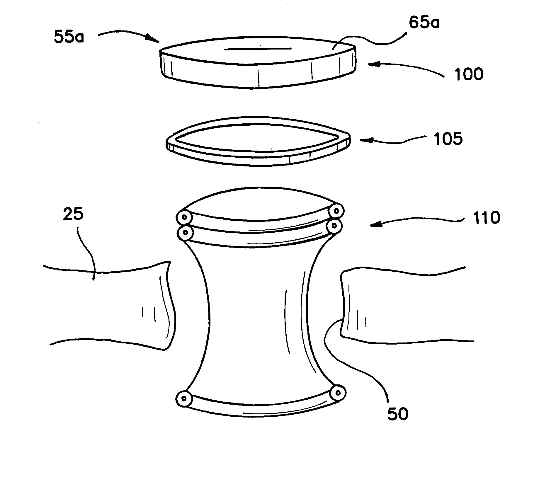
[0007] The deficiencies of the prior art are overcome with the present invention which includes a seal apparatus. In one embodiment, the device includes a valve structure formed of a gel including, for example, a thermoplastic base such as KRATON® and an oil. The resulting elastomer has excellent tear strength, high elongation, a very low durometer or hardness, and biocompatibility. The access device can function both as a zero seal and as an instrument seal. Furthermore, it can accommodate a full range of instruments having diameters up to about 37 mm. In another embodiment, several instruments of smaller diameter can be accommodated at the same time with a single access device.
[0008] Both tear resistance and sealing capability can be enhanced by encapsulating the gel in a sheath or otherwise providing circumferential reinforcement for the valve structure. Additives can be provided either on or in the gel to enhance properties such as lubricity, appearance, wound treatment and / or protection, anti-cancer protection and anti-microbial protection. Additional chemicals, compounds, pharmaceuticals or even mechanical devices can be mixed with or embedded in the gel material to vary chemical, pharmaceutical or physical properties of the access device.

Problems solved by technology

Unfortunately, the instrument seals have been able to accommodate only a narrow range of instrument diameters.

Method used


Image

  • Surgical instrument access device
  • Surgical instrument access device
  • Surgical instrument access device

Examples


Embodiment Construction

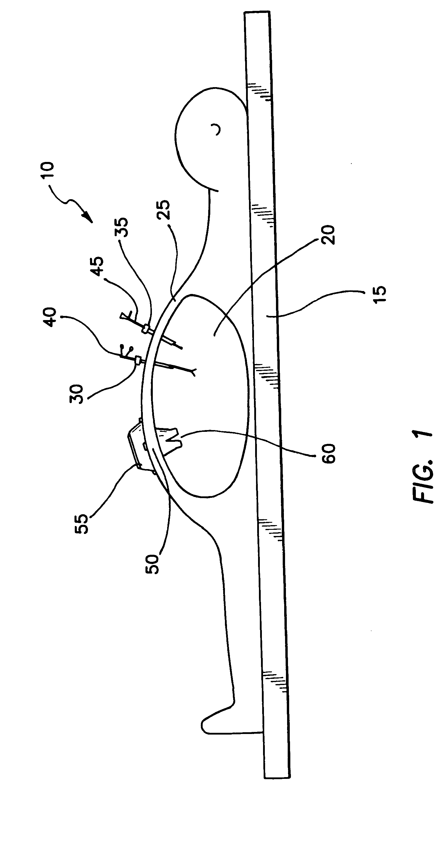
[0023] A patient is illustrated in FIG. 1 and designated generally by the reference numeral 10. The patient 10 is shown in a prone position on an operating table 15, where the operative procedure is performed within an abdominal cavity 20 with instrument access provided through an abdominal wall 25. In this type of operation, commonly referred to as laparoscopic surgery, trocars 30 and 35 are commonly used to provide minimally invasive access through the abdominal wall 25 for instruments such as a grasper 40 and an endoscope 45.

[0024] Although the specific focus of this disclosure will be on a preferred laparoscopic procedure, it will be noted that laparoscopic surgery is merely representative of a type of operation wherein a procedure can be performed in a body cavity with minimal access through a body wall.

[0025] Notwithstanding the foregoing generality, it is important to note that with respect to laparoscopic surgery, it is often desirable that instruments having diameters up ...


PUM


Abstract

A surgical access device includes a single valve that forms a seal with a body wall and provides an access channel into a body cavity. The valve has properties for creating a zero seal in the absence of an instrument as well as an instrument seal for an instrument having a diameter up to about 37 mm. The valve can include a gel material and the access channel can include a protective sleeve to provide for wound protection during insertion and withdrawal of a sharp surgical instrument. The valve further comprises a cap ring which may be inserted or molded with the gel material. The protective sleeve may be bonded or molded around an inner diameter of the cap ring. The protective sleeve may be a single tubular member, or may comprise a plurality of axially extending sleeve members having a plurality of axial slits. The protective sleeve and the cap ring may comprise of the same or different materials. The surgical access device further comprises at least one support ring disposed circumferentially of the valve forming a hollow space, and a wound retractor operatively placed in the hollow space. The wound retractor includes an inner ring, an outer ring, and a flexible sleeve connecting the inner ring and the outer ring.

Description

BACKGROUND OF THE INVENTION [0001] 1. Field of the Invention [0002] This invention relates generally to devices and other apparatus facilitating sealed access with surgical instruments across a body wall and into a body cavity. [0003] 2. Discussion of the Prior Art [0004] In several areas of surgery there exists a need to have mechanisms or devices that can seal a body cavity or space, and yet permit the introduction of surgical instruments of different sizes such as guidewires, endoscopes and staplers. Typical of these areas of surgery is laparoscopic surgery which relies on surgical instruments inserted through the abdominal wall to reach an operative site within the abdominal cavity. In order to increase space around the operative site within the cavity, insufflation gases are typically introduced to inflate the cavity and elevate the abdominal wall. This pressurizing of the abdominal cavity is referred to as pneumoperitoneum. In this context, the need to seal the body cavity or ...

Claims


Application Information

Patent Timeline
IPC IPC(8): A61B17/00A61B17/34
CPCA61B17/0293A61B17/3423A61B2017/00526A61B17/3498A61B17/3431A61B5/6889A61B5/6898A61B5/024A61B5/0507A61B5/08
Inventor KAHLE, HENRYADLPARVAR, PAYAMJOHNSON, GARY M.
Owner APPL MEDICAL RESOURCES CORP
Learn More