Refrigerating cycle device

a cycle device and refrigerant technology, applied in the field of refrigerating cycle devices, can solve the problems of toxicity, weak flammability of refrigerant, and drawback of having a large earth warming coefficient, and achieve the effect of efficient operation

Inactive Publication Date: 2005-03-24
PANASONIC CORP
View PDF5 Cites 15 Cited by
  • Summary
  • Abstract
  • Description
  • Claims
  • Application Information

AI Technical Summary

Benefits of technology

[0017] In view of the above-mentioned problems, with respect to a refrigerating cycle device which uses a CO2 refrigerant, it is an object of the present invention to provide a refrigerating cycle device and an operation method

Problems solved by technology

However, the HFC refrigerant has, as its material property, a drawback of having a large earth warming coefficient, while the HC refrigerant has a drawback that the refrigerant is strongly flammable although its earth warming coefficient is small.
Further, an ammonium refrigerant which has been used conventionally has a drawback that the refrigerant is weakly flammable and has toxicity although the earth warming coefficient is zero.
However, the CO2 refrigerant has a low critical temperature of 31.1° C. and hence, the condensation of the CO2 refrigerant is not generated at a high pressure side of a usual refrigerating cycle device.
However, the provision of the receiver at low pressure brings about drawbacks such as the increase of cost and the increase of volume.
To take a fact that, in an actual-use operation range, the pressure of the CO2 refrigerant becomes extremely high compared to the HCFC refrigerant and the HFC refrigerant which are used in t

Method used


Image

  • Refrigerating cycle device
  • Refrigerating cycle device
  • Refrigerating cycle device

Examples


embodiment 1

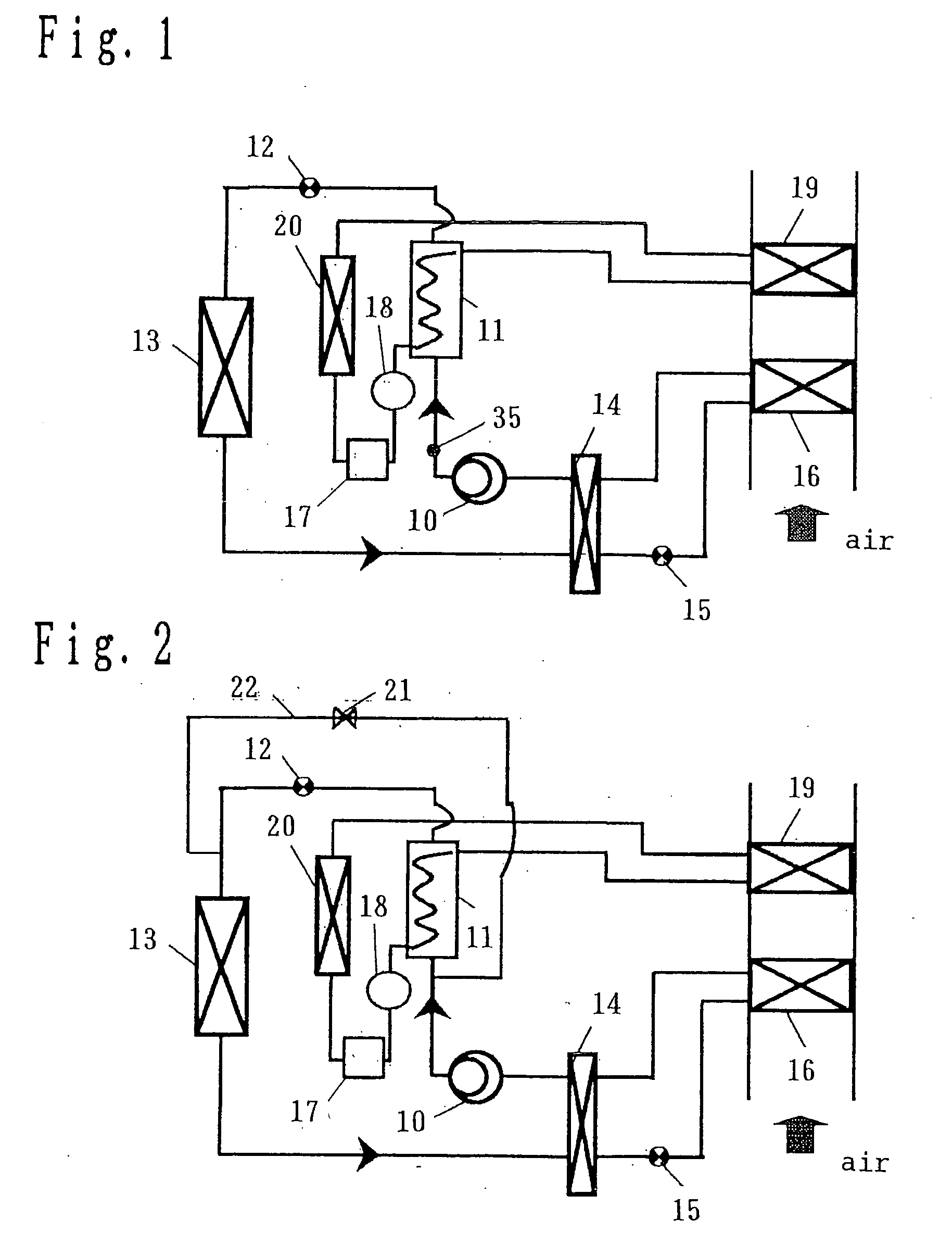
[0106]FIG. 1 is a constitutional view showing a refrigerating cycle device according to embodiment 1 of the present invention. The refrigerating cycle uses a CO2 refrigerant as a working fluid and adopts a compressor 10, a refrigerant-water heat exchanger 11, a first decompressor 12, a first heat exchanger 13, an internal heat exchanger 14, a second decompressor 15, a second heat exchanger 16 as basic constitutional elements thereof. An outlet-side line of the first heat exchanger 13 and a suction line of the compressor 10 which is arranged at an outlet of the second heat exchanger 16 are subjected to a heat exchange by the internal heat exchanger 14. On the other hand, the hot water cycle is constituted of a pump 18 which circulates hot water heated by the refrigerant-water heat exchanger, a heater core 19, a radiator 20 and a power engine 17.

[0107] Here, the operation of the refrigerating cycle device shown in FIG. 1 at the time of space cooling is explained.

[0108] First of all,...

embodiment 2

[0116] With respect to the embodiment 2 of the present invention, the manner of operation of the second decompressor 15 at the time of space heating / dehumidifying in the refrigerating cycle device shown in FIG. 1 is explained in conjunction with a flow chart shown in FIG. 8. The second decompressor 15 is a valve which is capable of adjusting a flow rate.

[0117] At the time of space heating / dehumidifying, a discharge temperature Td detected by compressor discharge temperature detection means 35 and a target set discharge temperature Tx are compared in step 40. Then, when Td is equal to or more than Tx, this implies a state that the refrigerant is in short and processing is advanced to step 41 in which a control is made to increase the degree of opening of the second decompressor 15. Accordingly, the intermediate pressure in the first heat exchanger 13 is lowered so as to lower the refrigerant holding quantity in the first heat exchanger 13 whereby the refrigerant shortage state can b...

embodiment 3

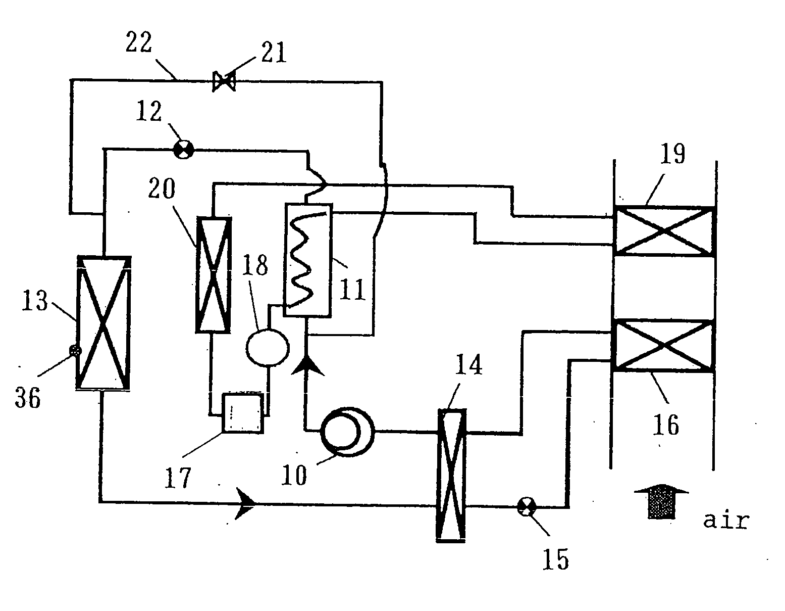
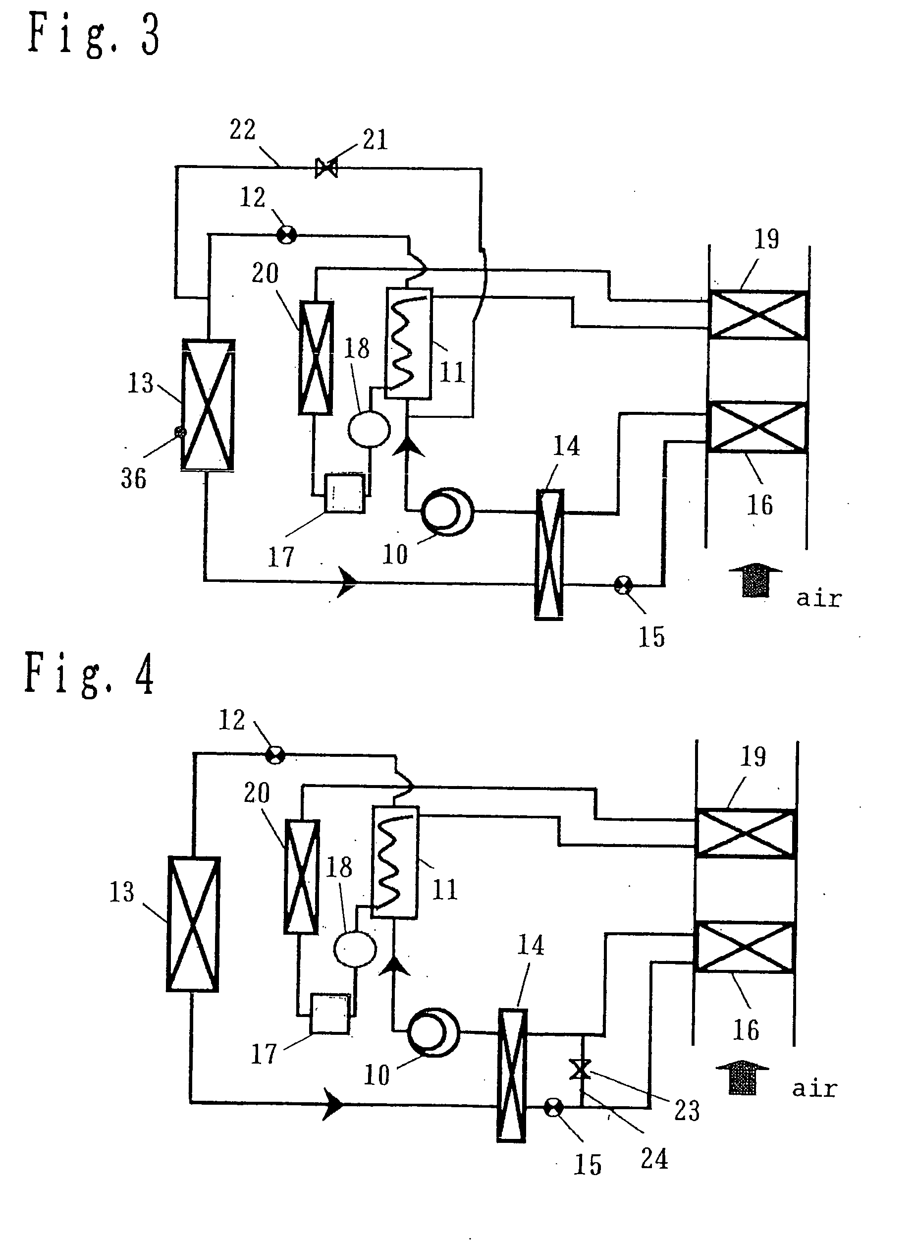
[0120]FIG. 2 is a constitutional view showing a refrigerating cycle device according to the embodiment 3 of the present invention. Points which make this embodiment different from the embodiment 1 are explained hereinafter. The refrigerating cycle device includes a first bypass circuit 22 which connects an outlet of the compressor 10 and an inlet of the first heat exchanger 13 by way of a first open / close valve 21.

[0121] First of all, the manner of operation of the refrigerating cycle device shown in FIG. 2 at the time of space cooling is explained. At the time of space cooling, the second decompressor 15 performs an operation as a decompressor while fully closing the first decompressor 12 and fully opening the first open / close valve 21. Accordingly, by making the refrigerant flow in the first bypass circuit 22 by opening the first open / close valve 21, it is possible to prevent the generation of pressure loss of the refrigerant in the refrigerant-water heat exchanger 11.

[0122] Nex...


PUM


Abstract

In a refrigerating cycle device using carbon dioxide as a refrigerant, there exists a problem that the provision of a receiver at a low-pressure side increases cost and volume due to a pressure resistance design necessary for ensuring safety. By adjusting a refrigerant holding quantity of a first heat exchanger in such a manner that a refrigerant pressure of the first heat exchanger 13 is changed by operating a first decompressor 12 and a second decompressor 15, an imbalance of a refrigerant quantity between time for space cooling and time for heating or dehumidifying can be alleviated and hence, it is possible to perform an operation of the refrigerating cycle device with high efficiency with a miniaturized receiver or without providing the receiver.

Description

TECHNICAL FIELD [0001] The present invention relates to a refrigerating cycle device which uses carbon dioxide as a working medium (hereinafter referred to as CO2 refrigerant). BACKGROUND ART [0002] Recently, in regard to a working medium used in a refrigerating cycle device, a conventional CFC refrigerant or an HCFC refrigerant which is considered to impart a harmful influence to an ozone layer is being replaced with an HFC refrigerant or an HC refrigerant whose ozone destruction coefficient is zero, wherein the HFC refrigerant or the HC refrigerant is used as a substitute refrigerant. [0003] However, the HFC refrigerant has, as its material property, a drawback of having a large earth warming coefficient, while the HC refrigerant has a drawback that the refrigerant is strongly flammable although its earth warming coefficient is small. Further, an ammonium refrigerant which has been used conventionally has a drawback that the refrigerant is weakly flammable and has toxicity althoug...

Claims


Application Information

Patent Timeline
IPC IPC(8): B60H1/00B60H1/32F24F3/153F25B5/04F25B6/04F25B9/00F25B40/00F25B47/00
CPCB60H1/00878F25B2700/21173B60H1/3217B60H2001/3248B60H2001/3255B60H2001/3285B60H2001/3288F24F3/1405F24F3/153F24F2003/1446F25B5/04F25B6/04F25B9/008F25B30/02F25B40/00F25B47/006F25B2309/061F25B2339/047F25B2341/0662F25B2400/0403F25B2400/0409F25B2400/19F25B2500/26F25B2600/02F25B2600/17F25B2700/21151F25B2700/21152F25B2700/2116F25B2700/2117B60H1/3205B60H1/32281F25B41/39F25B1/00F25B45/00
Inventor YAKUMARU, YUUICHIFUNAKURA, MASAMINISHIWAKI, FUMITOSHIOKAZA, NORIHO
Owner PANASONIC CORP
Why Eureka
Try Eureka