Ultrasonic transducer and method of joining an ultrasonic transducer

a transducer and ultrasonic technology, applied in the field of ultrasonic transducers, can solve the problems of not being used for e.g. copper alloys, not being used for joining materials, and the acoustic intermediate layer, which is usually placed between the plate and the disc, etc., to achieve the effect of reducing heat input, improving tightness, and simplifying manufacturing

Inactive Publication Date: 2005-03-24
SIEMENS AG +1
View PDF11 Cites 8 Cited by
  • Summary
  • Abstract
  • Description
  • Claims
  • Application Information

AI Technical Summary

Benefits of technology

[0008] The housing and the plate of the ultrasonic transducer are thus joined in a thermal joining process where the heat generation is caused by conducting an electrical current through the parts that are to be joined. Therefore, both housing as well as plate must be electrically conductive. Using the invention is has surprisingly turned out, that even though plate and piezoelectric disc are in close mechanical contact with each other during the joining process, the disc will not be thermally overloaded. Further, nor does the acoustic intermediate layer, which usually is placed between plate and disc, suffer, e.g. due to evaporation. The advantage in making use of an electrically based thermal joining process is that it gives a considerable lower heat input than compared to other welding methods. This increases the design possibilities of the transducer as the piezoelectrical disc can now be glued onto the plate whereafter joining can be done without affecting the glue strip considerably. This also applies to the use of grease instead of glue. The process is also faster than the manufacturing processes that have been used so far. The mechanical-electrical-thermal joining process is generally known under the name resistance welding or pressure welding, but also resistance soldering is a possibility. The temperature during joining can be lower or higher than the melting points of the used materials. Joining can take place with a melting zone in the parts used, whereby an actual welding and soldering takes place, or without melting zones causing a solid phase joining of the parts. Dependent on the process parameters there is a sliding transistion between the two cases. Resistance welding is well described in a paper at the conference “Sondertagung Widerstandsschweissen” by J. S. Hansen and J. Bruland, Danfoss A / S: “Verbessern der Buckelschweissneigung durch metallische Überzüge am Beispiel von Werkstoffen mit unterschiedlichen Eigenschaften”, Düisburg, Germany, 7 and 8 May 1998. In selecting the plate and the housing in different materials a simplified manufacture is achieved. A considerable drawback with known methods as laser and TIG welding is that they can not be used for e.g. copper alloys and not for joining materials which are of different kinds. Thus, a characteristic of the invention is that the plate and the housing can be chosen in different kinds of material. Mechanical joining methods like flanging, threading and the like are possible alternatives, but resistance welding, respectively resistance soldering, gives a better tightness and is mechanically and geometrically more simple. Thus, an inexpensive material can be used for the housing and another material for the plate, the latter material fulfilling the specifications for transmission.
[0009] A particularly good joining between the housing and the plate is obtained by surface coating one or both parts before joining. For example, in a chemical dip process or in an electrochemical bath the plate can be provided with a coating, and this coating is melted during the joining process by the high current and thereby functions as soldering material. This will result in a close tightening and a mechanically durable bond.
[0011] The housing of the ultrasonic transducer preferably consists of a copper alloy whereby brass is particularly preferred. It is less costly to manufacture a housing in brass than in stainless steel because metal cutting of brass is much easier. The manufacturing cost is about half of the price for stainless steel. Besides, it is possible to manufacture the brass housing through hot pressing with subsequent processing. At high numbers of work pieces this loweres the manufacturing cost further. If at the same time this combination of material is followed up by a surface coating as described above, a particularly corrosion resistant ultrasonic transducer is obtained.

Problems solved by technology

Further, nor does the acoustic intermediate layer, which usually is placed between plate and disc, suffer, e.g. due to evaporation.
A considerable drawback with known methods as laser and TIG welding is that they can not be used for e.g. copper alloys and not for joining materials which are of different kinds.

Method used


Image

  • Ultrasonic transducer and method of joining an ultrasonic transducer
  • Ultrasonic transducer and method of joining an ultrasonic transducer
  • Ultrasonic transducer and method of joining an ultrasonic transducer

Examples


Embodiment Construction

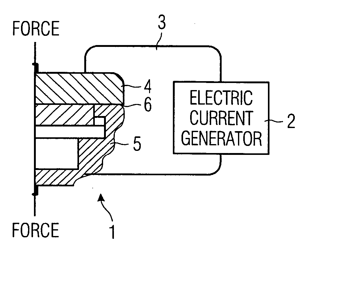
[0022]FIG. 1 is a schematic which shows how the ultrasonic transducer parts are joined according to the invention. A part of the ultrasonic transducer 1 is via conductors 3 connected to an electrical current generator 2. A mechanical force “Force” acts on the housing with a force of about 600 N, while the current generator sends a current of about 4 kA through plate 4 and housing 5. The thermal joining takes place in the contact area 6, which in this embodiment is annular. In other words, the protecting plate is welded in a circle onto the housing. Thus, local heating in the points of contact is created due to the electrical contact resistance when the parts are brought into contact with each other. The housing 5 preferably consists of dezincification resistant brass, while the plate 4 is made of stainless steel. Other combinations of materials are also possible. Thus, different kind of materials as free-cutting steel (i.e.machining steel) and stainless steel can be joined in a resi...


PUM


Abstract

The invention concerns an ultrasonic transducer, which is assembled from several parts. These parts are a protecting plate, a piezoelectric disc and a housing. Joining of the parts for transducers are normally done by means of TIG welding or laser welding, but these are relatively costly processes, which also has an impact on the transducer, especially the piezoelectric disc, due to the heat. In order to reduce the heat load and simultaneously simplify manufacturing an ultrasonic transducer is suggested, in which the protecting plate and the housing consists of electrically conducting materials of different kinds and where joining of housing and plate is done by using a mechanical force influence and an electrical current which flows through plate and housing. Also, a method for joining the parts of an ultrasonic transducer is described.

Description

CROSS REFERENCE TO RELATED APPLICATIONS [0001] This application is the US National Stage of International Application No. PCT / DK02 / 00794, filed Nov. 27, 2002 and claims the benefit thereof. The International Application claims the benefits of Danish application No. PA200101780 filed Nov. 30, 2001, both of the applications are incorporated by reference herein in their entirety.FIELD OF INVENTION [0002] The invention relates to an ultrasonic transducer for use at transmission of a sound in fluidic media. Transducers of this type are used in ultrasonic flowmeters which function according to either the transit-time principle or to the Doppler principle. The invention will primarily be used in ultrasonic flowmeters for liquids working according to the transit-time principle, however, it can be used in different types of ultrasonic flowmeters. BACKGROUND OF INVENTION [0003] Ultrasonic flowmeters that work according to the transit-time principle include one or more sets of ultrasonic trans...

Claims


Application Information

Patent Timeline
Patent Type & Authority Applications(United States)
IPC IPC(8): G10K9/22G10K11/00H04R17/00
CPCG10K9/22H04R17/00G10K11/004
Inventor BRUN, ESPEN GROENBORG
Owner SIEMENS AG
Why Eureka
Try Eureka