
High voltage cable for a miniature x-ray tube

a high voltage cable and x-ray tube technology, applied in the direction of power cables, cables, therapy, etc., can solve the problems of low stress level, inability to achieve polymer seals on x-ray tubes, etc., and achieve high stress and high initial strength

Inactive Publication Date: 2005-03-24
XOFT INC
View PDF20 Cites 44 Cited by
  • Summary
  • Abstract
  • Description
  • Claims
  • Application Information

AI Technical Summary

Benefits of technology

[0013] Polymers are traditionally used to electrically insulate conductors in a cable from each other and from external influences. However, because of the nature of the x-ray tube and its requirements to be capable of sustaining high vacuum and bake out temperature environments, polymer seals on the x-ray tube are not possible. An alternative to insulating conductors with the polymers is to insulate them with glass. While glass provides an effective electrical insulation, it is susceptible to fracture at low stress levels unless protected. When protection is applied at the time of insulating glass manufacture, strength of the glass is up to 100 times that typically observed. This high initial strength can be preserved through the application of surface protective coatings onto the glass. This technology is utilized in the manufacture of fiber optic cables to allow fibers to tolerate the high stresses that occur during fiber bending and handling. Herein, the concept of surface protection of glass insulated metallic conductors is disclosed.

Problems solved by technology

However, because of the nature of the x-ray tube and its requirements to be capable of sustaining high vacuum and bake out temperature environments, polymer seals on the x-ray tube are not possible.
While glass provides an effective electrical insulation, it is susceptible to fracture at low stress levels unless protected.

Method used


Image

  • High voltage cable for a miniature x-ray tube
  • High voltage cable for a miniature x-ray tube
  • High voltage cable for a miniature x-ray tube

Examples


Embodiment Construction

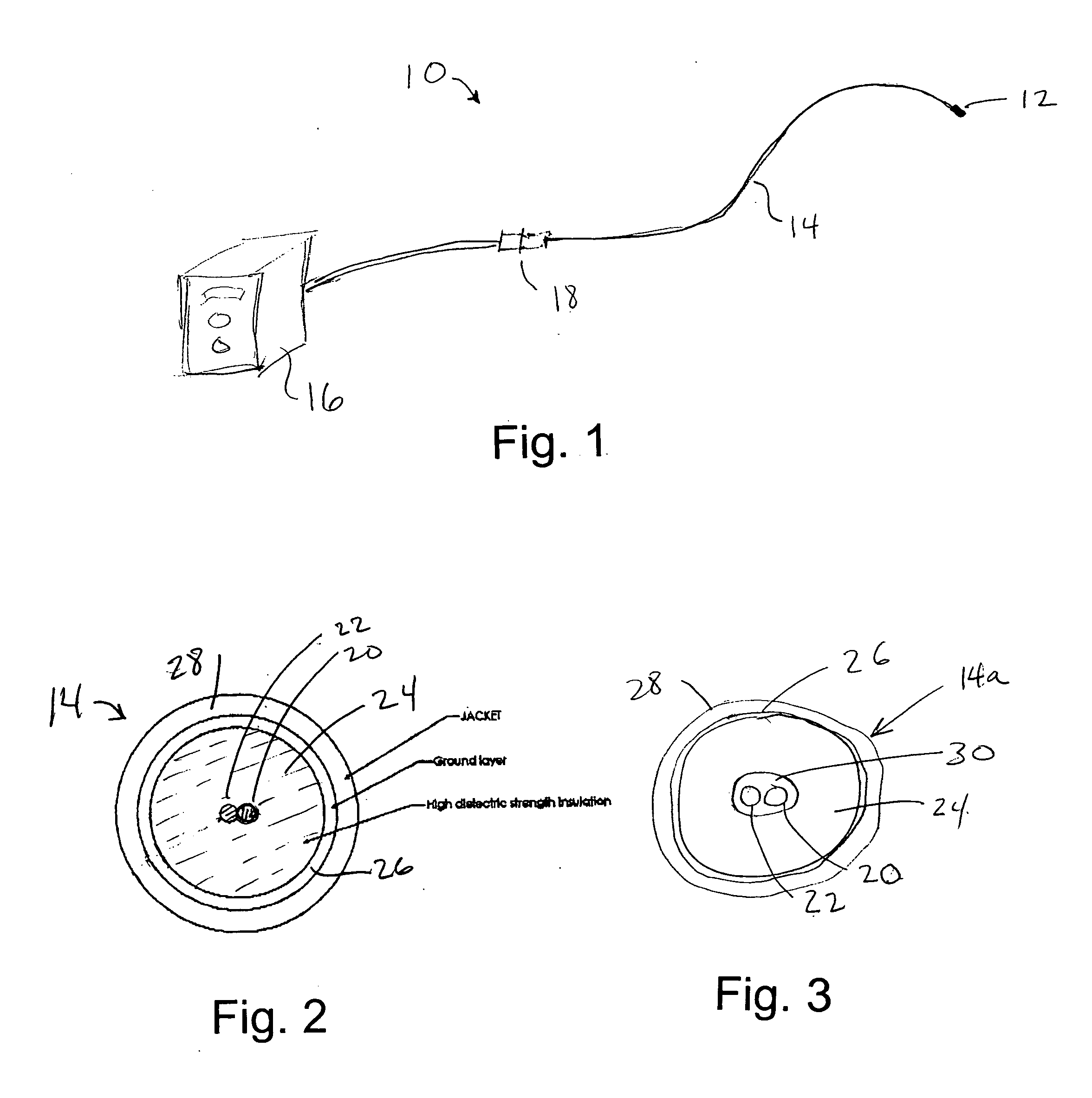
[0028] In the drawings, FIG. 1 shows schematically a system 10 according to the invention for administering x-rays using a switchable x-ray source. The system includes a miniature x-ray source 12 at the distal end of a cable 14, connected to a controller 16. The cable and x-ray source 14, 12 have important uses inside the human body, for various purposes discussed above. A connector 18 preferably is included, at a position which will remain outside a patient's body.

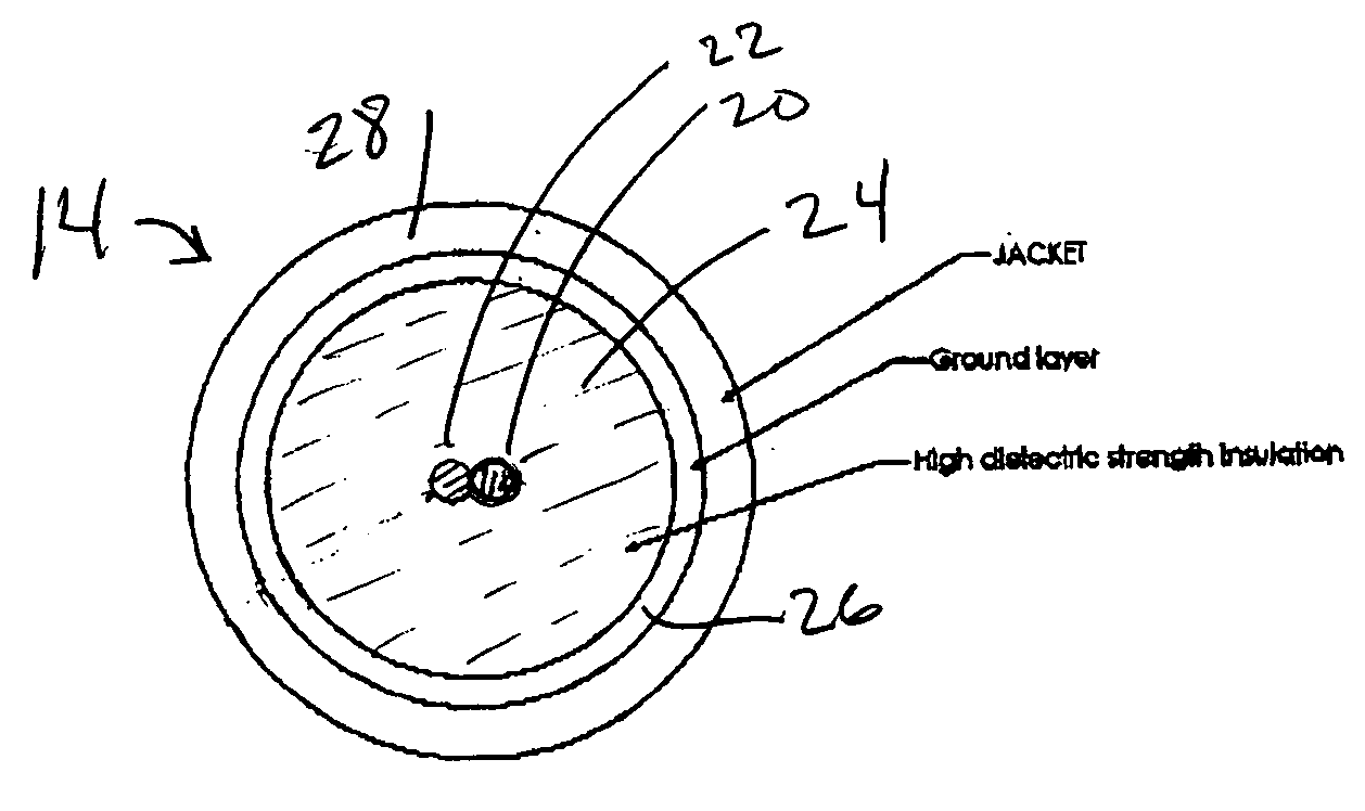
[0029] The cable 14 leading to the x-ray source 12 carries high voltage potential, up to about 50-60 kV, as well as carrying a low voltage cathode filament heater circuit. The low voltage conductors preferably also carry high voltage potential. The construction of such a cable, which must be small in diameter, flexible to travel around tight-radius curves and having a high dielectric property so as to resist breakdown, is the primary subject of the remaining drawings and of the discussion below.

[0030]FIG. 2 shows one em...


PUM


Abstract

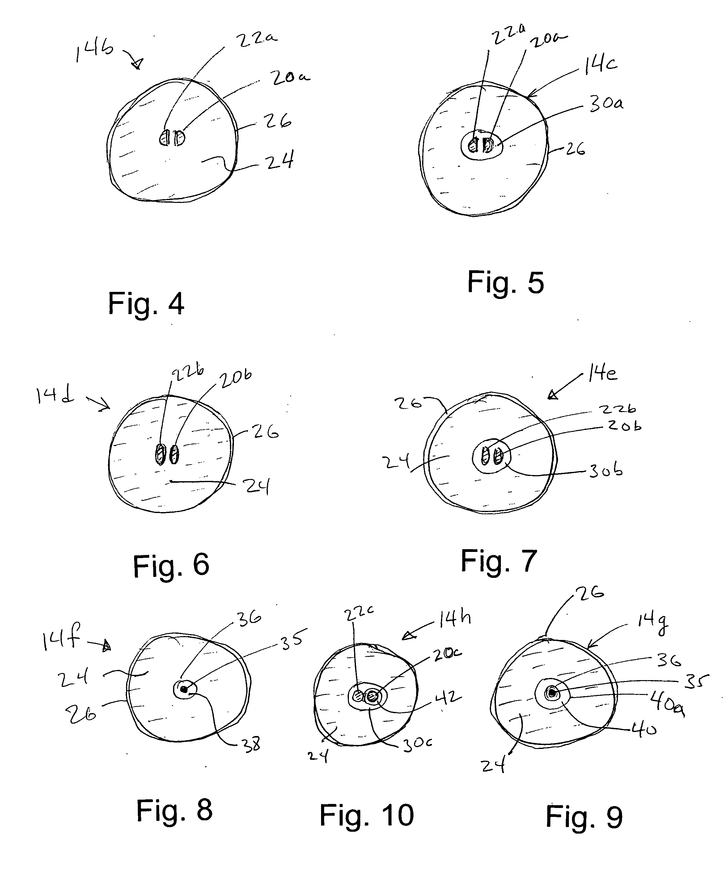
In a miniature x-ray tube, which may be on the order of approximately 1 mm in diameter or even less, a high voltage cable is provided in various embodiments for conducting current to the cathode of the x-ray tube and for conducting high voltage to the cathode and anode of the tube. In various embodiments of the cable, two conductors occupy a center region of the cable, packed as closely together as possible, in various shapes that are compact and present as smooth as possible an external shape for maximizing dielectric properties against the exterior high voltage ground, surrounding and generally concentric with the inner conductors. The inner conductors, which carry high voltage in opposition to the outer ground, can be in opposed D shapes, coaxial, two flattened conductors side by side, or simply a pair of cylindrical wires positioned as closely as possible. The space between the inner conductors and the outer ground can be occupied by a glass insulator, polymer, successive layers of polymers and adhesive, air, gas, vacuum or other dielectrics. A partially conductive region can surround the inner conductors.

Description

BACKGROUND OF THE INVENTION [0001] This application is a continuation in part of application Ser. No. 10 / 397,498, filed Mar. 26, 2003. [0002] This invention concerns the composition, structure and fabrication of a high voltage cable that leads to and is connected to a miniature x-ray source, for applications including post-operative radiation of breast tissue and treatment within various lumens of the human body, including blood vessels. [0003] Miniature or small x-ray tubes for human therapeutic treatment are discussed in several prior patents, including U.S. Pat. Nos. 5,854,822, 5,621,780 and 6,319,188, as well as co-pending application Ser. No. 10 / 397,498, commonly owned with this application. Such small x-rays tubes have been proposed or developed for the purpose of treating tumors within surgical openings in the body, for treatment within blood vessels using a catheter that contains the tube, and for other radiation treatments within the body. The cited pending application desc...

Claims


Application Information

Patent Timeline
IPC IPC(8): A61N5/10H01J9/04H01J9/24H01J35/06H01J35/32
CPCA61N5/1001A61N5/1002H01J9/04H01J2235/164H01J35/06H01J35/32H01J2235/02H01J9/24
Inventor LOVOI, PAUL A.SMITH, PETER C.LIM, ALEX
Owner XOFT INC
Learn More