Electron beam system and electron beam measuring and observing methods
- Summary
- Abstract
- Description
- Claims
- Application Information
AI Technical Summary
Benefits of technology
Problems solved by technology
Method used
Image
Examples
first embodiment
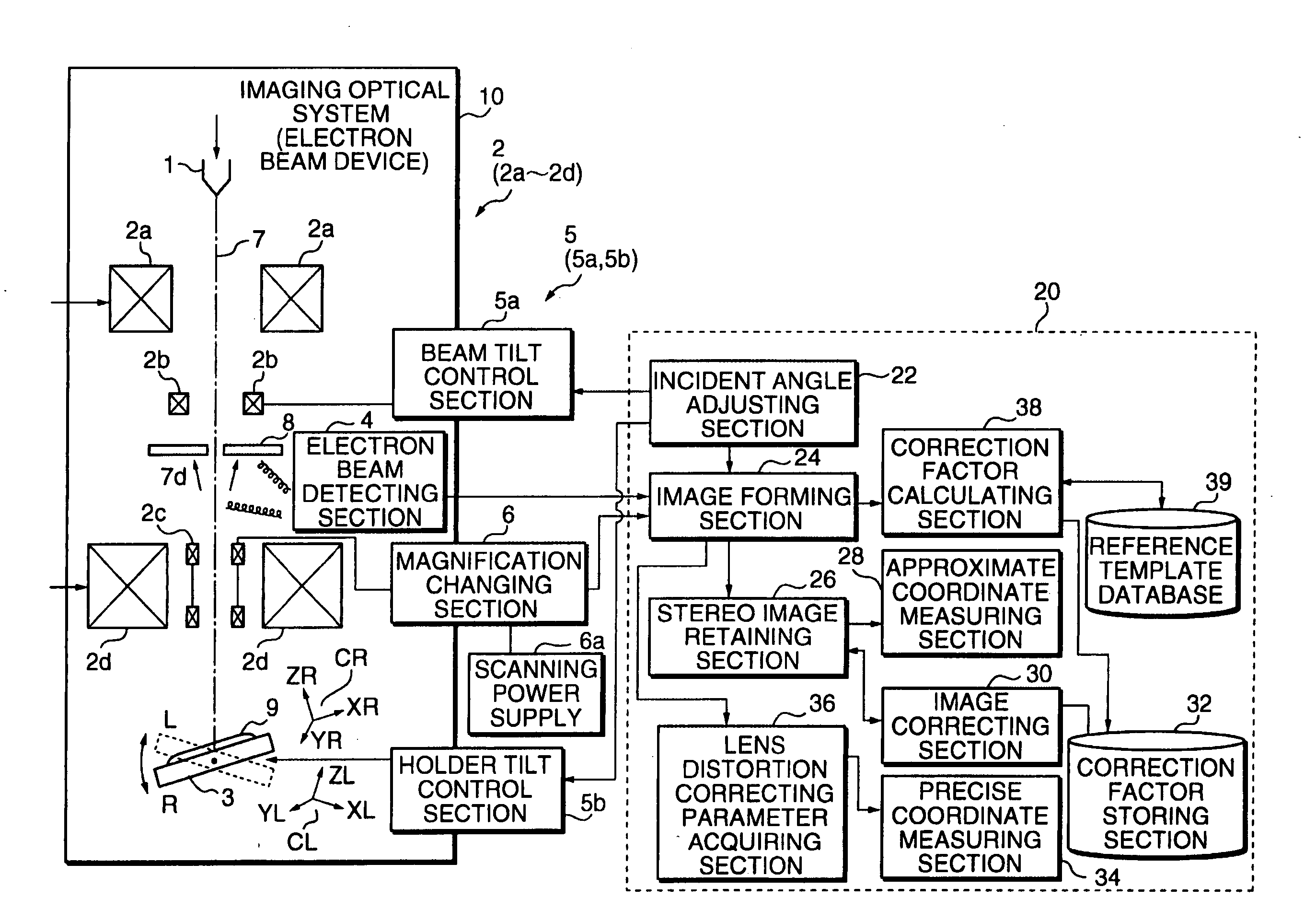
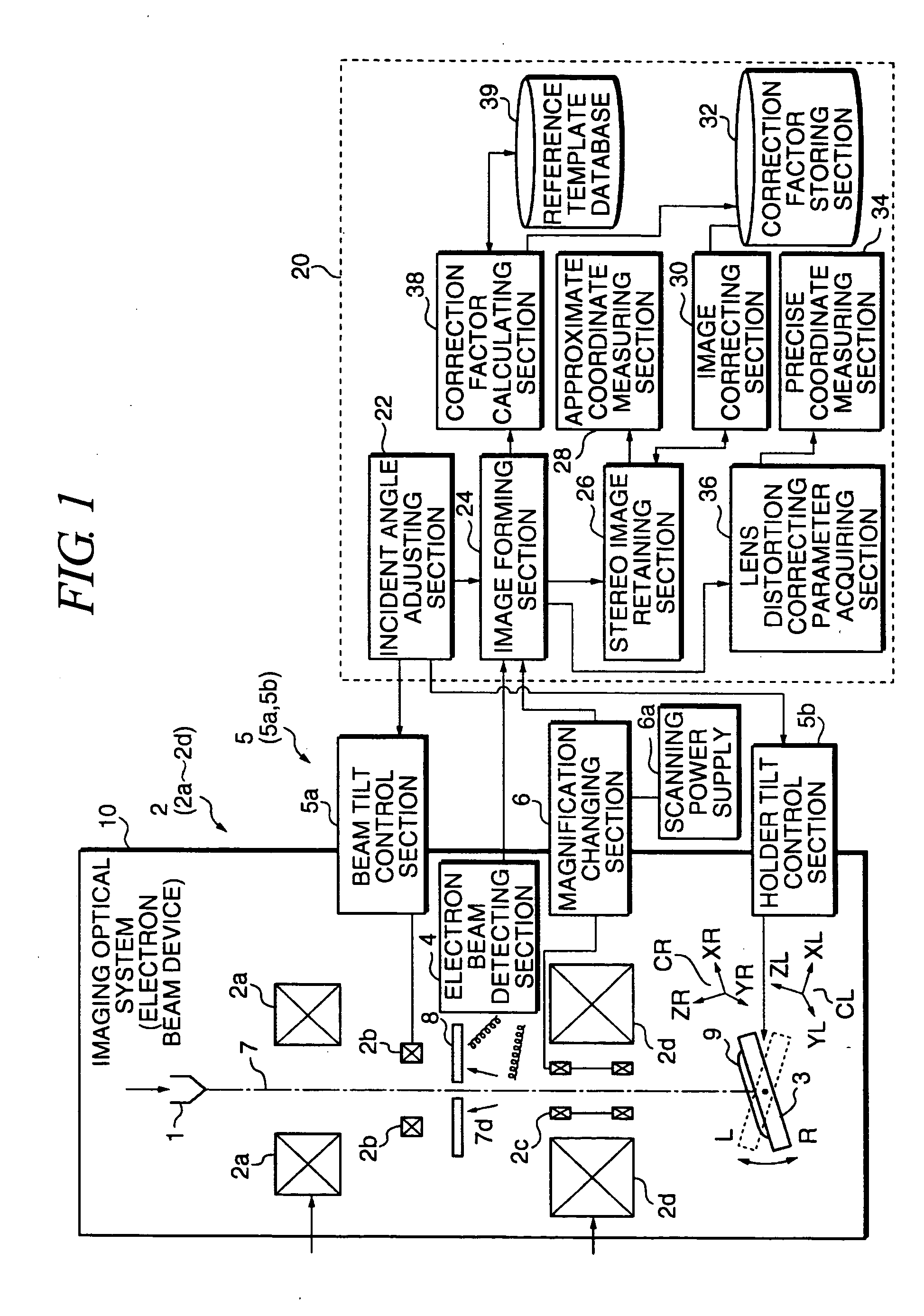
Description will be hereinafter made of the embodiments of this invention with reference to the drawings. FIG. 1 is a block diagram illustrating the structure of a first embodiment of this invention. In the first embodiment, the rotational angle of the holder for holding an object is adjusted to adjust the tilt angle of the object so that a stereo image of the object can be obtained. As shown in the drawing, an electron beam device 10 (scanning electron microscope) as an imaging optical system has an electron beam source 1 for emitting an electron beam 7, an electron optical system 2 for irradiating the electron beam 7 on an object 9, a sample holder 3 for tiltably holding the object 9, a magnification changing section 6 for changing the magnifying power of the electron optical system 2, a scanning power supply 6a for supplying electric power to the magnification changing section 6, a detector 4 for detecting the electron beam 7, a holder tilt control section 5b as a tilt control s...
second embodiment
Referring now to FIG. 19, a case will be described in which a three-dimensional template is used as a reference template. The process is generally the same as in the first embodiment except that the procedure for obtaining the height correcting parameters is suitable for a three-dimensional reference template. FIG. 19 is a flowchart used to explain the process of photographing and acquiring images of a three-dimensional reference template. A three-dimensional reference template 9c is placed on the sample holder 3 (S400). Then, the holder tilt angle control section 5b sends a tilt control signal to the sample holder 3 and the incident angle adjusting section 22 adjusts the incident angle of the electron beam 7 relative to the object 9 (S410). When the reference template 9c is three-dimensional, the interval between the tilt angles may be large or coarse as has been described with FIG. 9. The tilt angles which the incident angle adjusting section 22 sets in step S410 are so determine...
third embodiment
Description will be made of a third embodiment with reference to FIG. 20. The third embodiment relates to the procedure for observing a sample with images thereof photographed by the electron beam device 10 using the height correcting parameters obtained in the first or second embodiment. FIG. 20 is a flowchart used to explain the procedure for observing a sample with images of the sample photographed by the electron beam device 10. A measuring object 9 is placed on the sample holder 3 (S500). The incident angle adjusting section 22 tilts the sample holder 3 at desired angles (S510). The tilt angles are determined based on what part of the measuring object 9 is necessary to be viewed or the required measurement accuracy. For example, the sample holder 3 and the electron beam 7 make the first and second tilt angles relative to each other. The electron beam measuring device 20 acquires stereo pair images of the measuring object 9 (S520). The stereo pair image data detected with the e...
PUM
 Abstract
Description
Claims
Application Information
 - R&D
- Intellectual Property
- Life Sciences
- Materials
- Tech Scout
- Unparalleled Data Quality
- Higher Quality Content
- 60% Fewer Hallucinations
Browse by: Latest US Patents, China's latest patents, Technical Efficacy Thesaurus, Application Domain, Technology Topic, Popular Technical Reports.
© 2025 PatSnap. All rights reserved.Legal|Privacy policy|Modern Slavery Act Transparency Statement|Sitemap|About US| Contact US: help@patsnap.com


