Logic circuit whose power switch is quickly turned on and off

a logic circuit and power switch technology, applied in logic circuit coupling/interface arrangement, power consumption reduction, pulse technique, etc., can solve the problems of leakage current, reduced operating speed, and significant decline in the capability of the resistor driv

Inactive Publication Date: 2005-03-24
RENESAS ELECTRONICS CORP
View PDF19 Cites 12 Cited by
  • Summary
  • Abstract
  • Description
  • Claims
  • Application Information

AI Technical Summary

Benefits of technology

[0016] Other and further objects, features and advantages of the invention will appear more fully from the following description.

Problems solved by technology

However, if the power supply voltage is decreased, the transistor drive capability will considerably decline and the operating speed will go down as the power supply voltage becomes close to the transistor's threshold voltage.
As the threshold voltage is lowered, leakage current, which should be incommensurably smaller than the switching power, would increase exponentially and come to consume non-negligible power.
It is expected that as the tendency towards further fine fabrication and lower power supply voltages continues, more power will be consumed for current leakage than for switching.
Whereas the switching power is consumed only during operation of the circuit, power consumption due to leakage current continues while the power is on.
Another problem is that when the circuit is switched on after it has not been used for a long time, the voltage levels of output nodes of transistors may be inverted almost at the same time and at that time there occurs a flow of short-circuit current.
This short-circuit current becomes one of the major reasons for increase in power consumption.
Therefore, it would be impossible to turn on and off the power as frequently as necessary or quickly.

Method used


Image

  • Logic circuit whose power switch is quickly turned on and off
  • Logic circuit whose power switch is quickly turned on and off
  • Logic circuit whose power switch is quickly turned on and off

Examples


Embodiment Construction

[0048] Next, preferred embodiments of the present invention will be described in detail referring to the accompanying drawings illustrating relevant logic circuits. The same reference numerals given in FIGS. 1 to 31 designate the same or similar elements.

[0049]

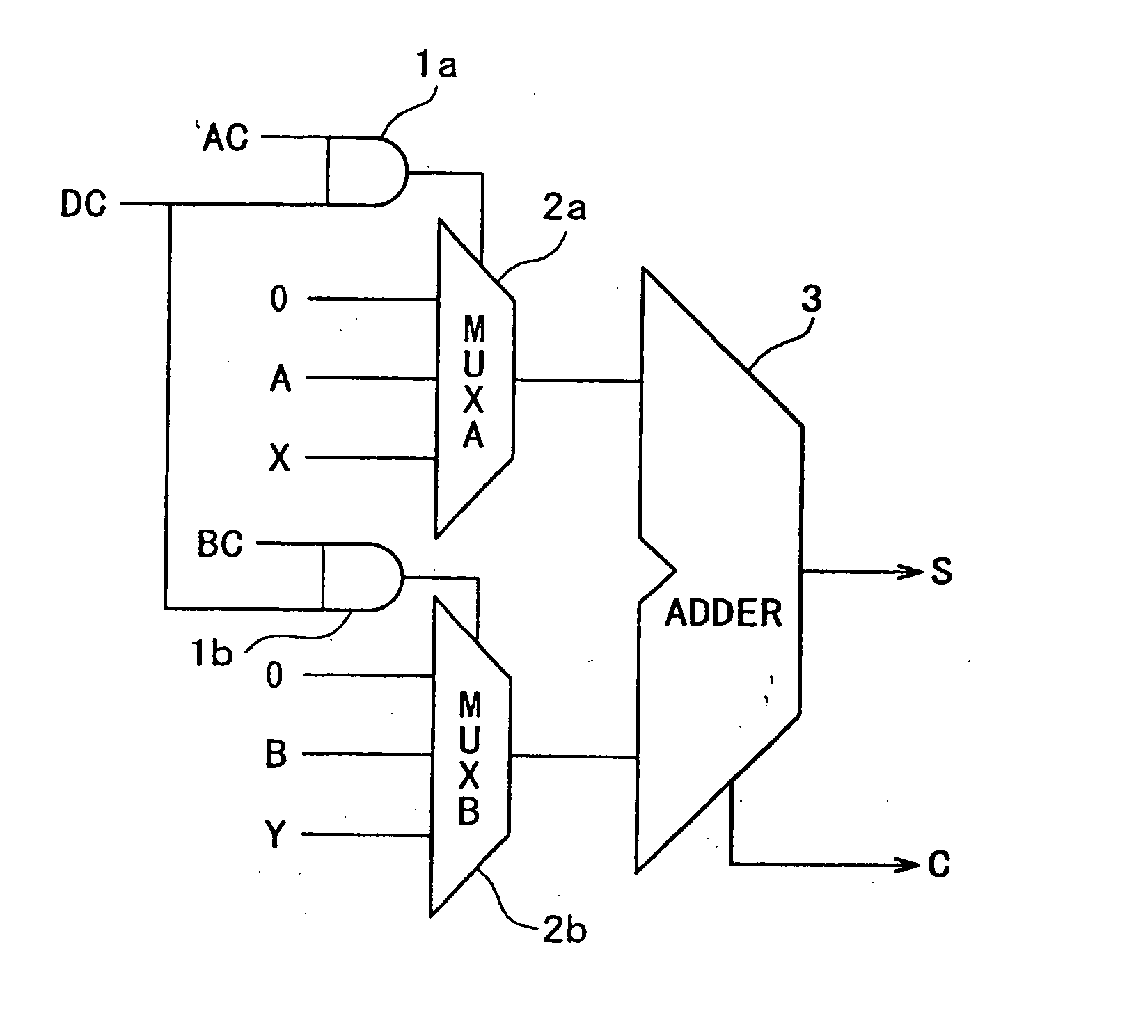
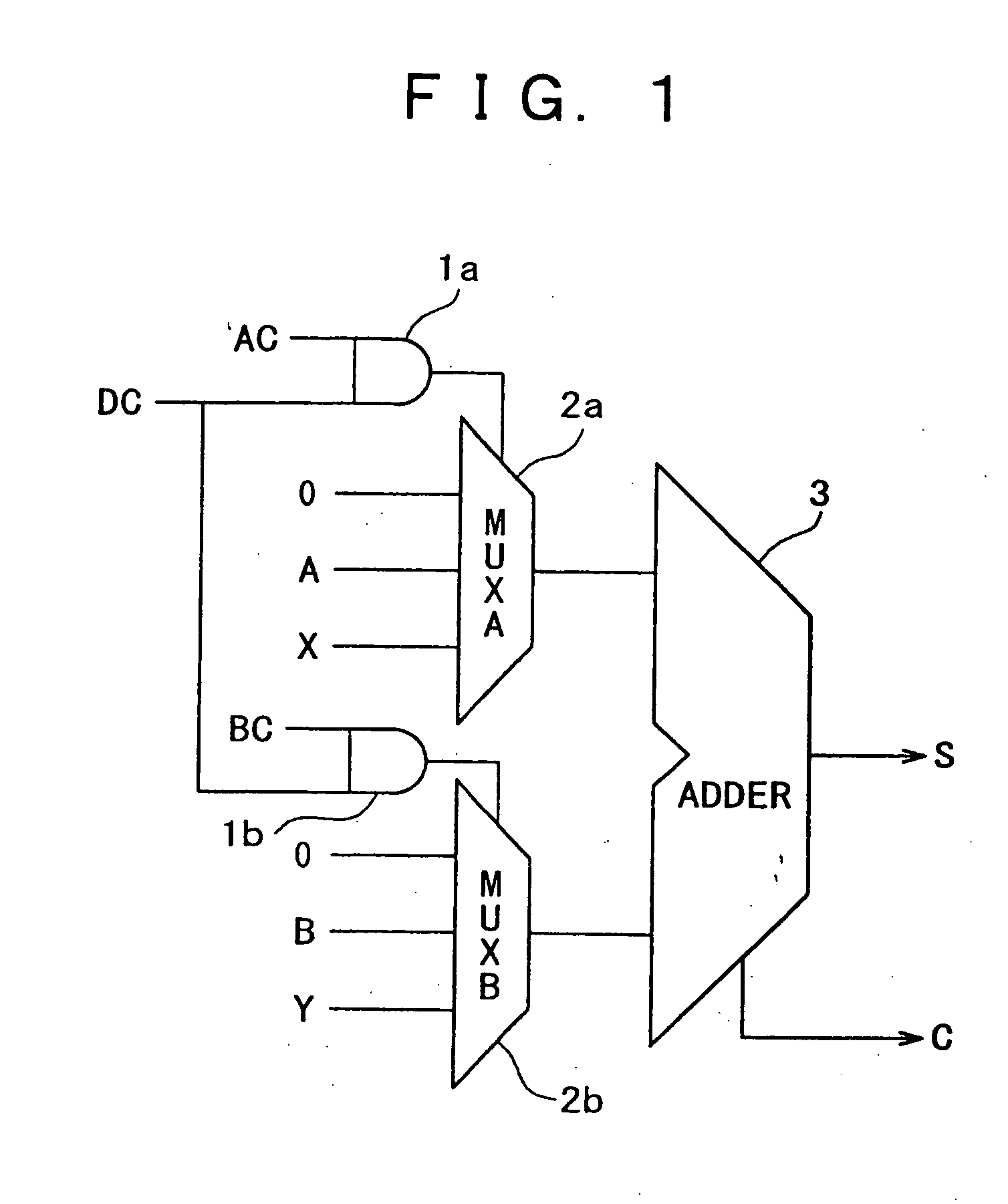
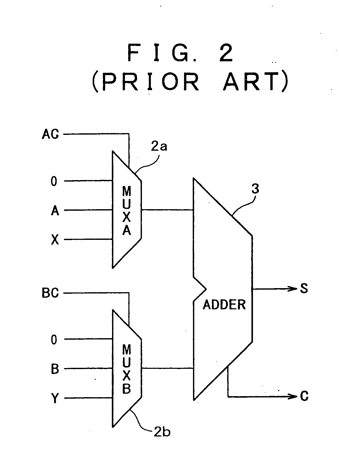
[0050] The basic structure of an adder according to the present invention is shown in FIG. 1. In the figure, 1a and 1b represent control gates on the A and B sides for input of a control signal for specific status DC, respectively; 2a a multiplexer (MUX) as a selector which selects input signals 0, A, X on the A side according to input select signal AC; 2b a multiplexer as a selector which selects input signals 0, B, Y on the B side according to input select signal BC; and 3 an adder which receives the results of multiplexers 2a and 2b and outputs sum S and carry C. This basic structure is a variation of the conventional structure, where the control gates for specific status 1a and 1b are respectively added before the gates f...


PUM


Abstract

The present invention is to provide a logic circuit which assures short-circuit current reduction by using a gate which uniquely fixes the level of each node and also reduces leakage current so that the power is turned on and off quickly. Logic gates of the subject logic circuit are divided into first-type logic gate and second-type logic gates. The first-type logic gate outputs high potential under the specific status and the second-type logic gate outputs low potential under the specific status. Under the state that the high potential is supplied to the first-type logic gates and the low potential is supplied to the second-type logic gates, the power switch MOS is turned on. Further, in case of the adder, the specific status is equal to selecting a constant as an input of the adder. For general logic circuit, specific flip-flops are introduced to implement this specific status.

Description

BACKGROUND OF THE INVENTION [0001] 1. Field of the Invention [0002] The present invention relates to a logic circuit suitable for use in a semiconductor integrated circuit, and particularly to a logic circuit composed of CMOS (Complementary Metal Oxide Semiconductor) circuitry, which consumes less power when the power is turned on or the circuit is not in use, and enables the power switch to be quickly turned on and off. [0003] 2. Description of the Related Art [0004] With the growing demand for fine-fabrication and low power consumption, the power supply voltage for semiconductor integrated circuits has been decreasing year by year. In particular, the spread of portable battery-powered equipment such as mobile phones has been accelerating the demand for low power consumption. In semiconductor integrated circuits, particularly CMOS circuits, power is mostly consumed as switching power. The switching power is in proportion to the square of the power supply voltage and decreasing the ...

Claims


Application Information

Patent Timeline
Patent Type & Authority Applications(United States)
IPC IPC(8): H01L27/04H01L21/822H03K17/04H03K17/16H03K17/687H03K19/00H03K19/0948
CPCH03K19/0016H03K19/0948
Inventor ARAKAWA, FUMIO
Owner RENESAS ELECTRONICS CORP
Why Eureka
Try Eureka