
Charge signal converting amplifier

a technology of converting amplifier and charge signal, which is applied in the direction of electric control, instruments, machines/engines, etc., can solve the problems of affecting the accuracy of measurement, so as to reduce the amount of calculation load, prevent the effect of zero level fluctuations

Inactive Publication Date: 2005-03-24
SUBARU CORP
View PDF6 Cites 4 Cited by
  • Summary
  • Abstract
  • Description
  • Claims
  • Application Information

AI Technical Summary

Benefits of technology

[0019] Accordingly, it is an object of the present invention to provide a charge signal converting amplifier which prevents fluctuations of zero levels upon converting a charge signal outputted from a charge generating sensor into a voltage and which reduces calculating loads necessary for a signal processing.

Problems solved by technology

However, the measurement with the charge generating sensor always has such a drifting problem of a zero point due to a charge leakage or a temperature change.
This impedes the accurate measurement.
However, there are problems to be solved for the application to the mass production vehicles.
Consequently, the numerous processing capacity must be added to the on-board device and the device increases in size and the costs increase.

Method used


Image

  • Charge signal converting amplifier
  • Charge signal converting amplifier
  • Charge signal converting amplifier

Examples


Embodiment Construction

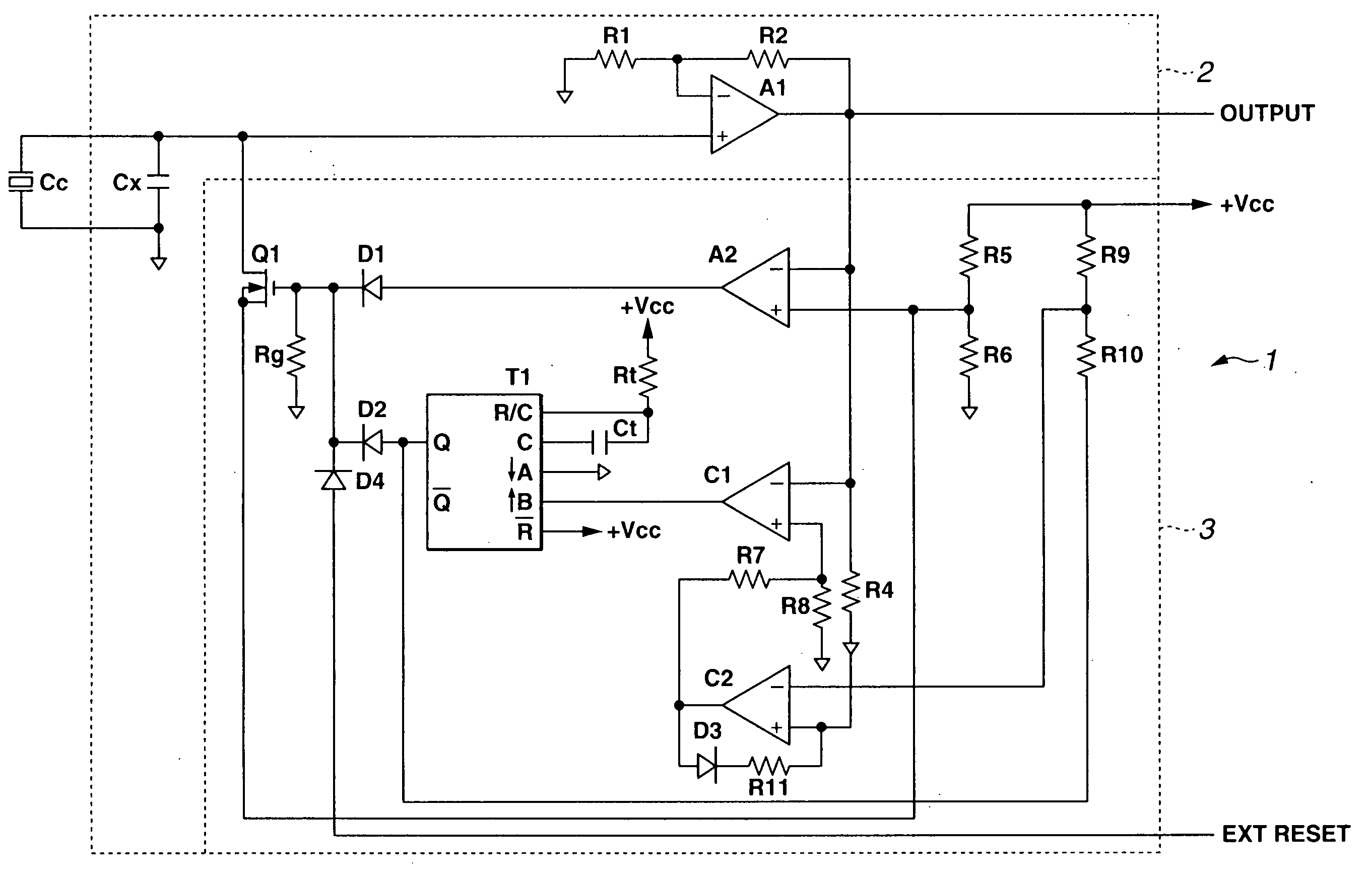
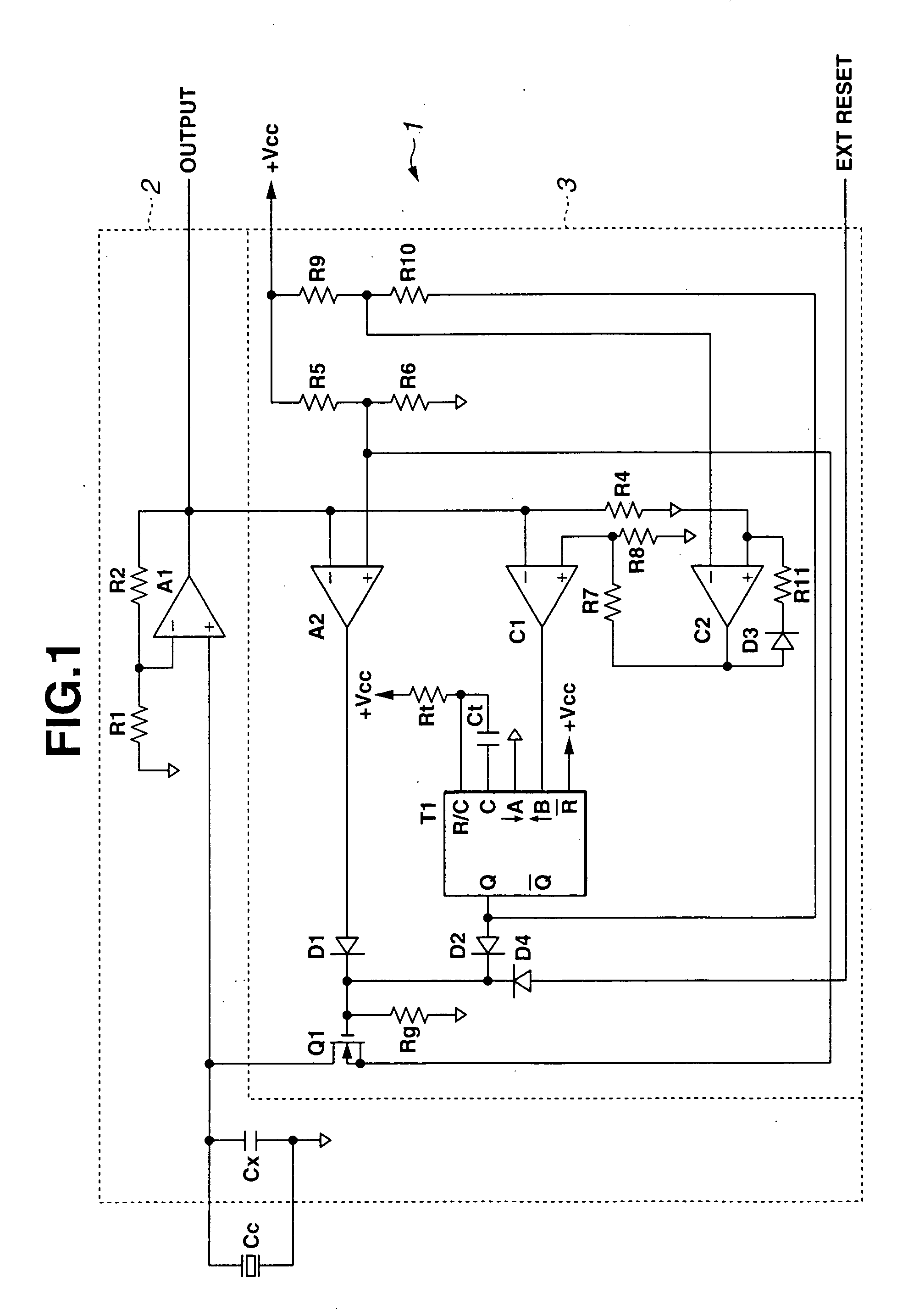
[0030] A charge signal converting amplifier according to the present invention can respond to positive and negative polarities of input charges. Further, the charge signal converting amplifier can respond to either one of an inverting amplifier or a normal (non-inverting) amplifier. FIG. 1 shows a basic equivalent circuit of the normal amplifying for inputting the positive charges. Referring to FIG. 1, a reference symbol Cc denotes an equivalent capacitor indicating the generated charges of a charge generating sensor such as a pressure sensor using a piezoelectric element, and reference symbol 1 denotes the charge signal converting amplifier which receives an input from the equivalent capacitor Cc.

[0031] The charge signal converting amplifier 1 comprises: a signal converting circuit 2 which converts a charge signal into a voltage signal; and an automatic correcting circuit 3 which automatically corrects positive and negative drifts at a zero point due to charge leakages or temperat...


PUM

PropertyMeasurementUnit
pressureaaaaaaaaaa
frequencyaaaaaaaaaa
circuit voltageaaaaaaaaaa

Abstract

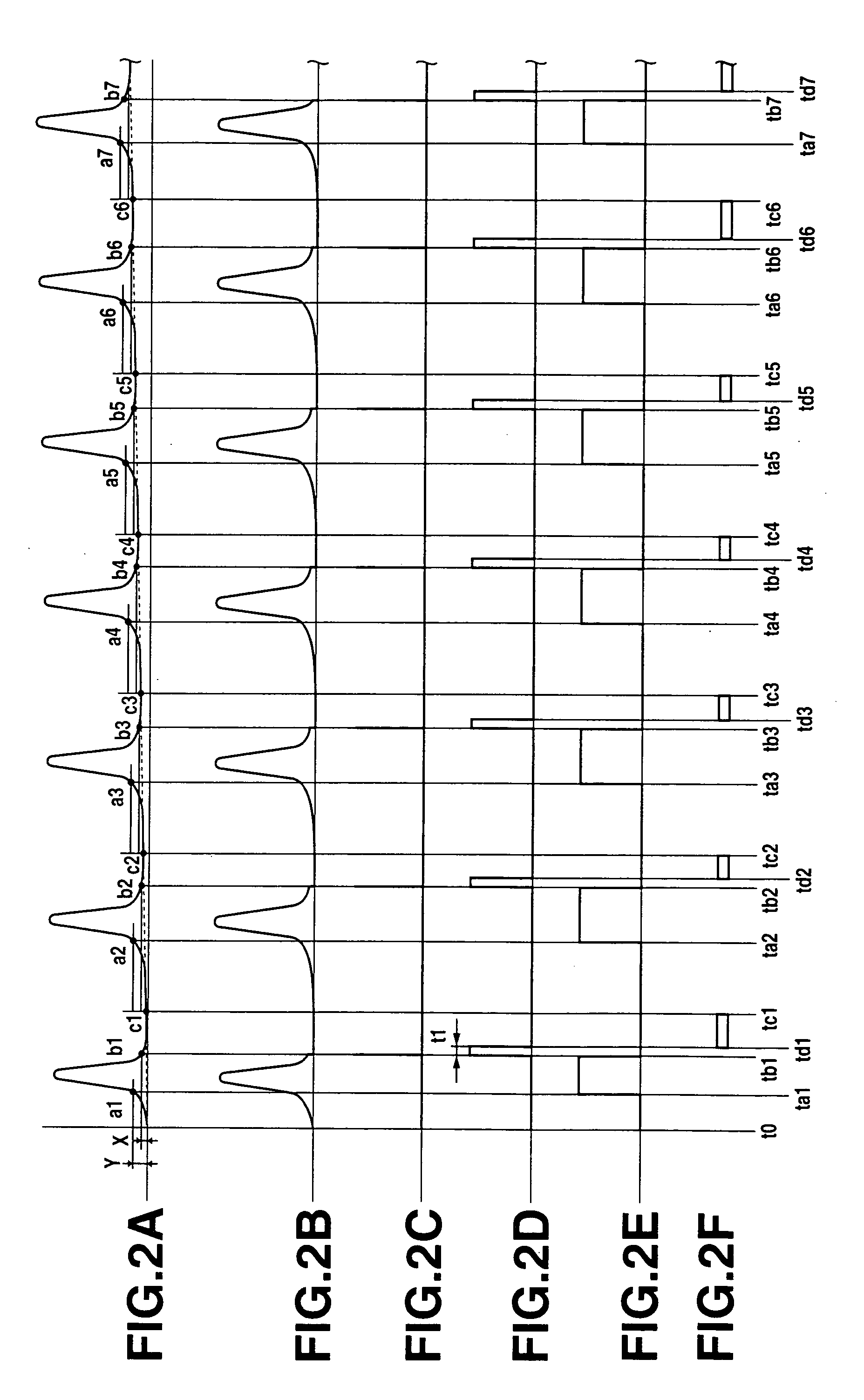
Positive charges of a sensor element are stored in a capacitor for converting a voltage, are converted into a positive voltage by an amplifier, and then are outputted. When the polarity of the charges of the sensor element are inverted to the negative, the charges inversely flow from the capacitor for converting the voltage and feed back to an equivalent capacitor of the sensor element, and an output of the amplifier reduces and returns to a zero-point, an automatic correcting circuit makes an FET conductive and the charges are discharged in order to prevent the fluctuation of the zero-point level due to the negative drift.

Description

[0001] The disclosure of Japanese Patent Application No. 2003-326821 filed on Sep. 18, 2003 including the specification, drawings and abstract is incorporated by reference in its entirely. BACKGROUND OF THE INVENTION [0002] 1. Field of the Invention [0003] The present invention relates to a charge signal converting amplifier which converts a charge signal outputted from a charge generating sensor into a voltage. [0004] 2. Description of the Related Art [0005] A charge generating sensor such as a piezoelectric element generates a charge in proportion to a load magnitude which is mechanically applied. Generally, the charge generating sensor is suitable for measuring a continuous dynamic pressure, and is used for a pressure sensor (cylinder pressure sensor) for measuring a combustion pressure in a cylinder. In order to extract a signal from the charge generating sensor, the signal from the charge generating sensor is generally converted into a voltage signal by using an amplifier with ...

Claims


Application Information

Patent Timeline
Patent Type & Authority Applications(United States)
IPC IPC(8): F02D45/00G01L9/08G01L23/10G01L23/22H03F3/34
CPCG01L23/10G01L9/085G01L23/222
Inventor KASHIWASE, HAJIMEWATANABE, HIROMICHIYOKOYAMA, HIROSHI
Owner SUBARU CORP
Learn More