Uv-bandpass filter and application tp uv-detecting apparatus or light-emitting apparatus

a filter and bandpass technology, applied in the field of uvbandpass filters, can solve the problems of difficult application to uv-detecting apparatuses for detecting light in the uv-region, hard detection of uv-rays, etc., and achieve the effects of excellent wavelength selectivity, simple configuration, and excellent transmission characteristi

Inactive Publication Date: 2005-03-24
HAMAMATSU PHOTONICS KK
View PDF5 Cites 10 Cited by
  • Summary
  • Abstract
  • Description
  • Claims
  • Application Information

AI Technical Summary

Benefits of technology

[0006] The inventors have found that a single silver layer having an excellent transmission characteristic with respect to only light in a specific wavelength region included in the UV-region in a wide wavelength band ranging at least from 200 nm to 3000 nm can be obtained when transmission characteristics of a thin silver film is appropriately regulated by controlling its thickness, thereby achieving the present invention, whose object is to provide a UV-bandpass filter comprising a structure having an excellent wavelength selectivity with a simple configuration while enabling wide applications, a UV-detecting apparatus including the same, and a UV source (light-emitting apparatus) including the same.
[0007] The UV-bandpass filter according to the present invention is an optical filter for selectively transmitting therethrough light having a wavelength included in a specific UV-region having a wavelength ranging from 200 nm to 400 nm, preferably a wavelength ranging from 250 nm to 400 nm, more preferably a wavelength ranging from 300 nm to 360 nm, while absorbing or reflecting light having a wavelength excluding the specific UV-region, wherein the UV-bandpass filter includes a thin silver film comprising an entrance face and an exit face opposing the entrance face, for emitting the light having a wavelength included in the specific UV-region in the light having reached the entrance face, and reduces the ratio of light excluding the UV-region to 10% or less in the transmitted light emitted from the exit face.

Problems solved by technology

When an optical filter having such transmission characteristics is utilized in an inexpensive light-receiving device mainly made of silicon, for example, having a light-receiving sensitivity up to near 1000 nm so as to be employed in a UV-detecting apparatus for detecting light included in the UV-region, UV-rays are hard to detect due to the transmission of light in the IR-region.
SHO 60-252303 utilizes a silver film as a reflecting mirror, it merely eliminates light in the UV-region by absorption, and is hard to apply to UV-detecting apparatus for detecting light in the UV-region.

Method used


Image

  • Uv-bandpass filter and application tp uv-detecting apparatus or light-emitting apparatus
  • Uv-bandpass filter and application tp uv-detecting apparatus or light-emitting apparatus
  • Uv-bandpass filter and application tp uv-detecting apparatus or light-emitting apparatus

Examples


second embodiment

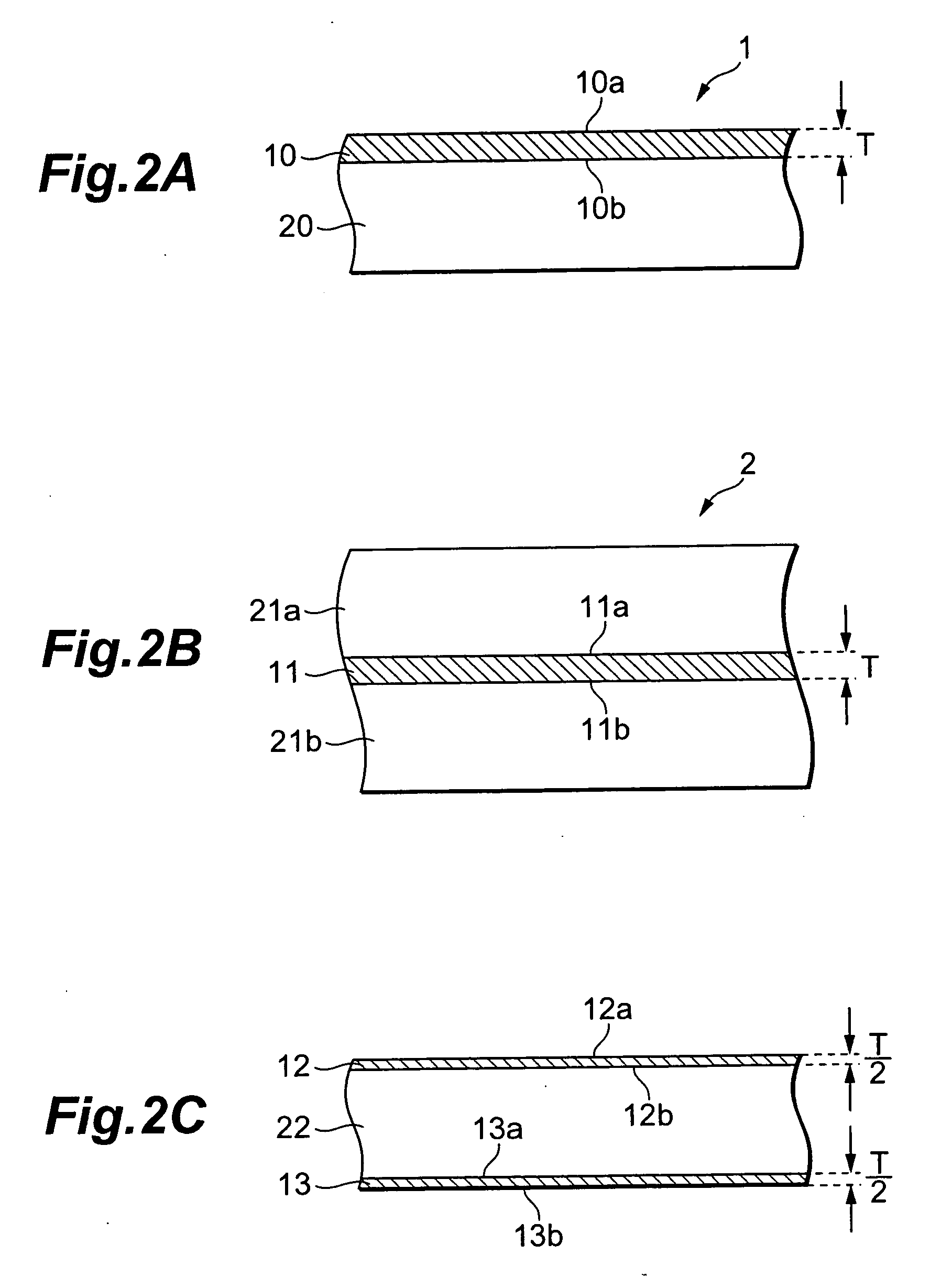
[0031] The thin silver film 10 has a thickness T of 70 nm or more, preferably 80 nm or more, so as to suppress the transmittance with respect to light having wavelengths excluding the specific UV-region to 10% or less, preferably 5% or less, in the UV-bandpass filter 2 as well. On the other hand, it is necessary for the thickness T of the thin silver film 10 to be set to 250 nm or less in order to secure a transmittance of 5% or more with respect to light having a wavelength included in the specific UV-region.

third embodiment

[0032] The UV-bandpass filter 3 shown in FIG. 2C comprises a UV-transmitting member 22 and thin silver films 12, 13, each having a thickness T / 2, formed on opposite main faces of the UV-transmitting member 22. The thin silver film 12 comprises an entrance face 12a and an exit face 12b for emitting light in the UV-region in the light having reached the entrance face 12a. On the other hand, the thin silver film 13 comprises an entrance face 13a and an exit face 13b for emitting light in the UV-region in the light having reached the entrance face 13a. It is not always necessary for the thin silver films 12, 13 to have the same thickness as long as their total thickness is T. Also, the number of thin silver films is not limited to 2 (the laminate structure may have two or more thin silver films having a total thickness of T).

[0033] The total thickness (T) of the thin silver films 12, 13 is designed so as to become 70 nm or more, preferably 80 nm or more, in order to suppress the transm...

first embodiment

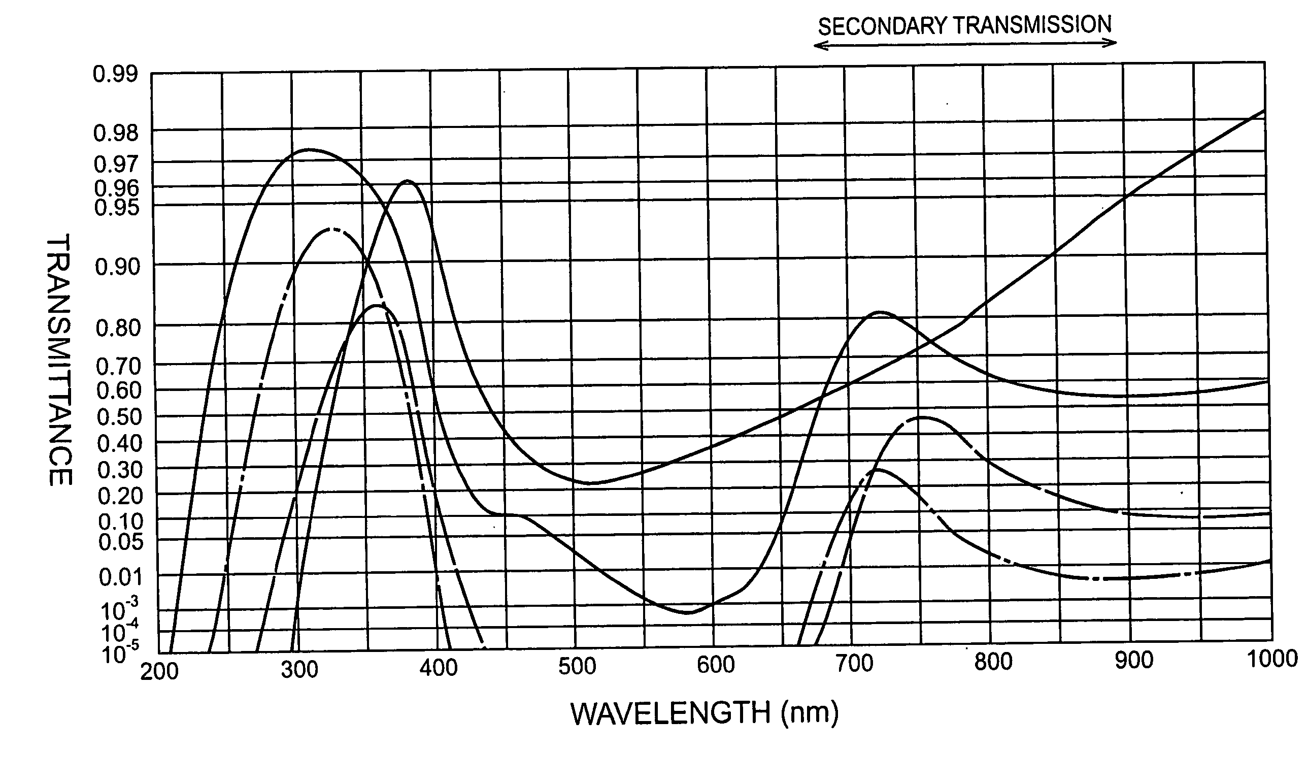
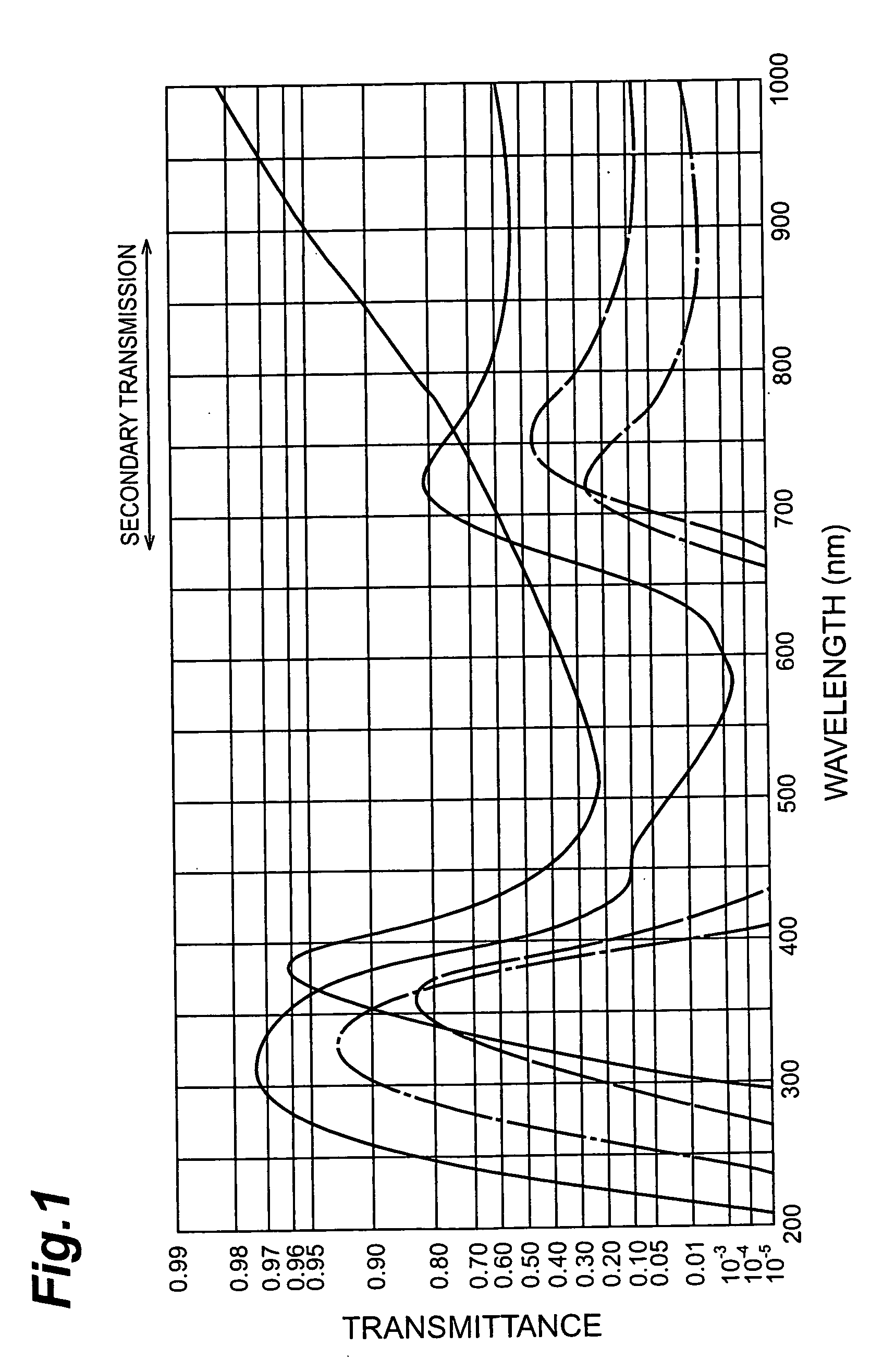
[0034] The inventors prepared 11 kinds of samples having respective thicknesses (12.8 nm to 400.0 nm) different from each other, and measured transmission characteristics of these samples. Each of thus prepared samples comprised a structure similar to that of the UV-bandpass filter 1 shown in FIG. 2A, and was made by forming a thin silver film with a predetermined thickness on a surface of silica glass. FIG. 3 is a graph showing wavelength dependence characteristics concerning five kinds of thin silver films having thicknesses of 12.8 nm, 28.8 nm, 46.4 nm, 59.2 nm, and 78.4 nm, respectively; whereas FIG. 5 is a graph showing wavelength dependence characteristics concerning six kinds of thin silver films having thicknesses of 80.4 nm, 106.4 nm, 135.2 nm, 160.8 nm, 241.2 nm, and 400.0 nm, respectively.

[0035] In FIG. 3, curves G210, G220, G230, G240, and G250 show wavelength dependence characteristics of transmittance concerning thin silver films having thicknesses of 12.8 nm, 28.8 nm...


PUM


Abstract

The present invention relates to a UV-bandpass filter for transmitting therethrough light having a wavelength included in a UV-region, and the like. The bandpass filter is an optical filter including a thin silver film; whereas the thin silver film comprises an entrance face and an exit face opposing the entrance face, for emitting light having a wavelength included in a specific UV-region whose wavelength ranges from 250 nm to 400 nm in the light having reached the entrance face, and has such a thickness as to yield a transmittance of 10% or less with respect to light having a wavelength excluding the specific UV-region.

Description

TECHNICAL FIELD [0001] The present invention relates to a UV-bandpass filter which selectively transmits therethrough light having a wavelength included in a UV-region, a UV-detecting apparatus including the same, and a UV source (light-emitting apparatus) including the same. BACKGROUND ART [0002] Conventionally known as an optical filter having a transmission characteristic with respect to light in a UV-region is, for example, one made by SCHOTT Corporation (catalog number: 3555eIX / 84) having transmission characteristics such as those shown in FIG. 1. While FIG. 1 shows transmission characteristics of four kinds of optical filters, each tends to exhibit transmission peaks in both UV- and IR-regions. [0003] On the other hand, silver films have been known to exhibit excellent spectral reflection characteristics with respect to light excluding the UV-region. Known as an optical filter utilizing such a silver film is, for example, one using a silver film as a reflecting mirror disclose...

Claims


Application Information

Patent Timeline
Patent Type & Authority Applications(United States)
IPC IPC(8): G01J1/04G02B5/20G01J1/02G02B5/22G02B5/26
CPCG01J1/0488G02B5/208G01J1/429G01J1/08G02B5/20
Inventor SAKAKIBARA, MASAYUKIMORISHITA, MASARU
Owner HAMAMATSU PHOTONICS KK
Why Eureka
Try Eureka