Exhaust gas purification system
- Summary
- Abstract
- Description
- Claims
- Application Information
AI Technical Summary
Benefits of technology
Problems solved by technology
Method used
Image

Examples
first embodiment
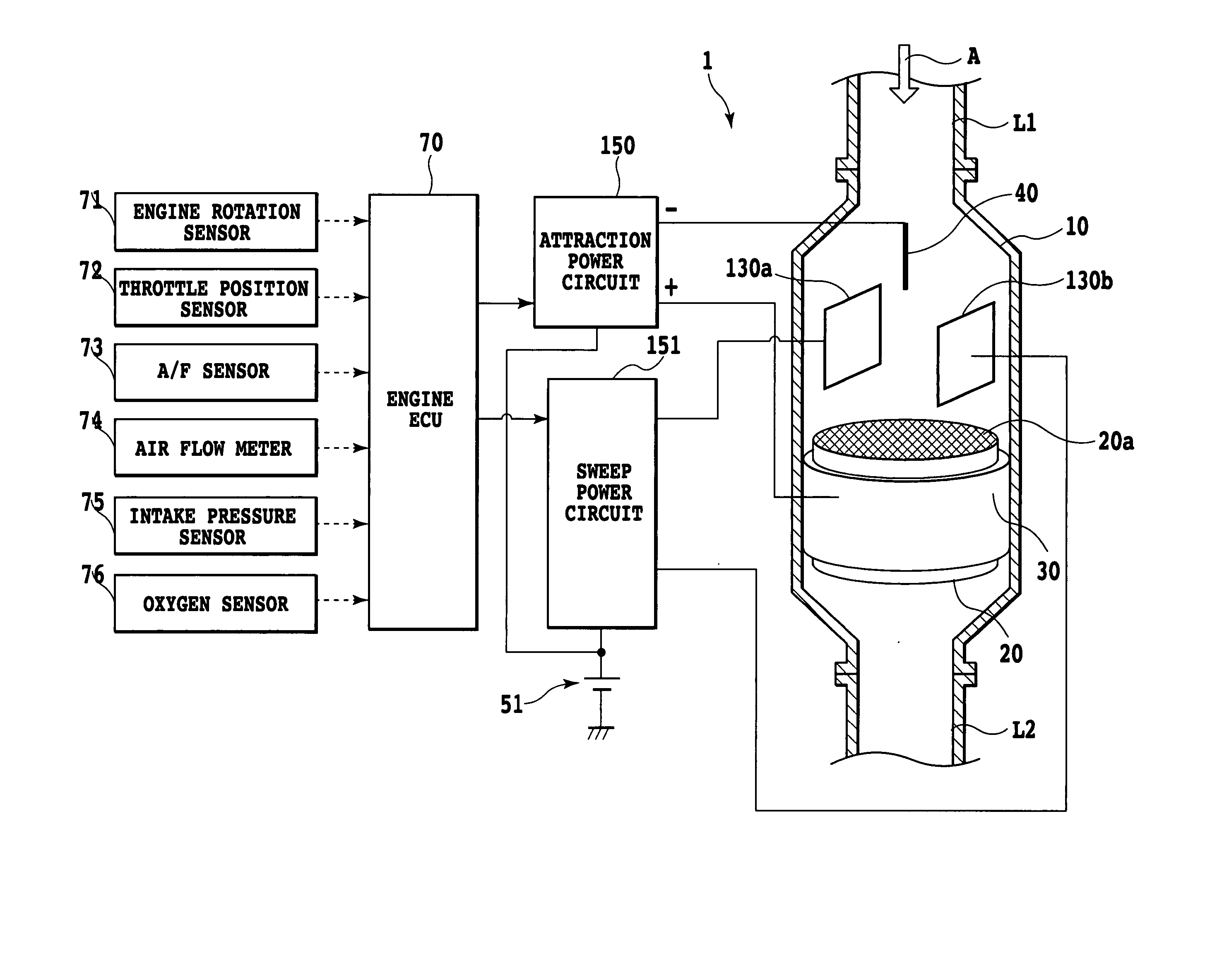
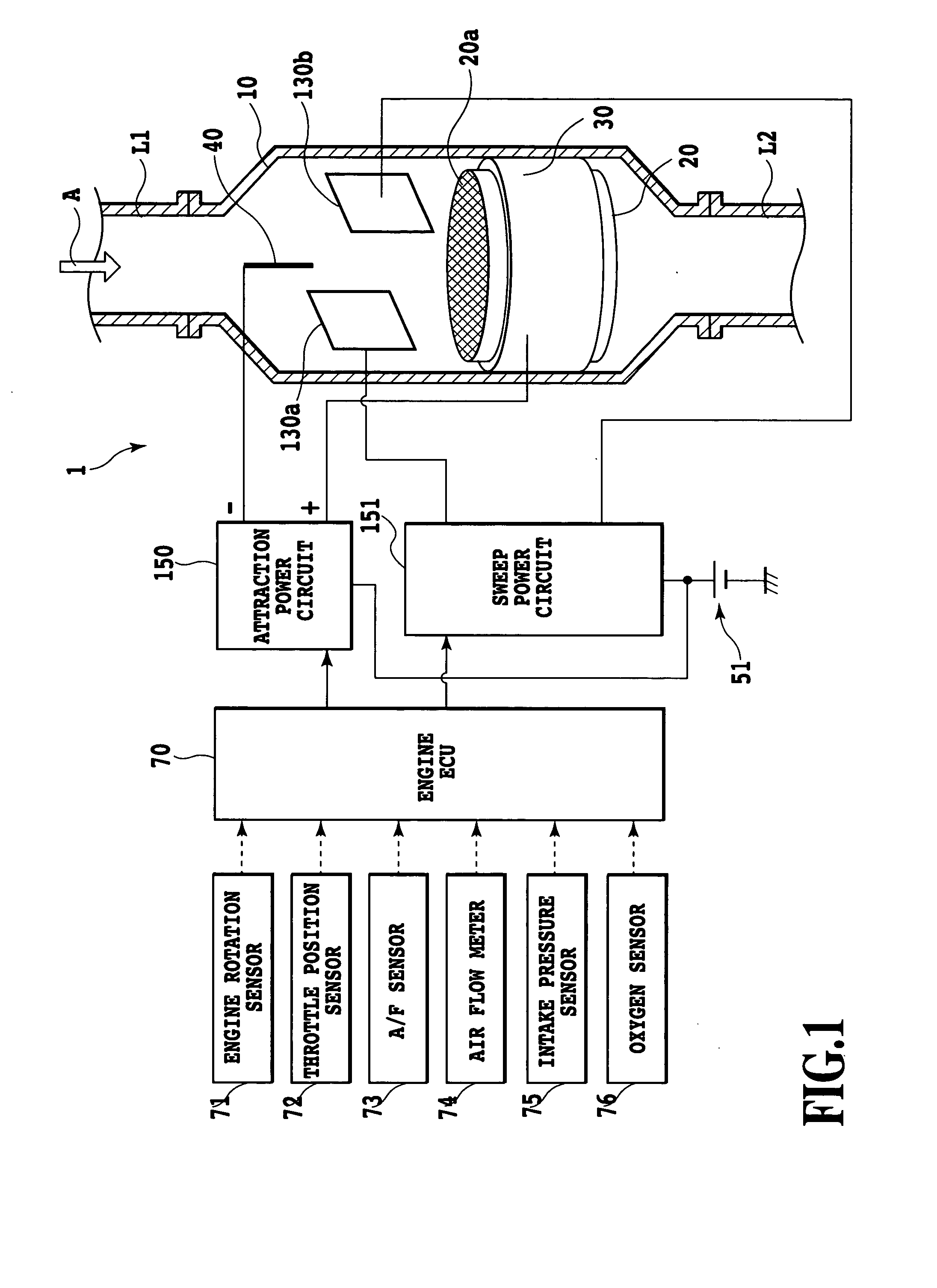
[0023] Preferred embodiments of the present invention will be described with reference to the accompanying drawings. FIG. 1 shows an exhaust gas purification system of the present invention. An exhaust gas purification system 1 is built into an exhaust path of a not shown internal combustion engine for purifying exhaust emissions discharged from a combustion chamber of the engine.
[0024] As shown in FIG. 1, the exhaust gas purification system 1 includes a purification container 10 of metal formed into a substantially cylindrical shape. An upstream end of the purification container 10 is connected to a not shown exhaust manifold of the engine by way of an exhaust pipe L1. A downstream end of the purification container 10 is connected to a catalytic device and a not shown muffler by way of an exhaust pipe L2, and thus is in communication with the outside environment. The exhaust emissions discharged from the combustion chamber of the engine are introduced through the exhaust pipe L1 in...
second embodiment
[0036] An exhaust gas purification system of a second preferred embodiment of the present invention will be described. The first preferred embodiment explained above uses one pair of sub-electrodes 130a and 130b. It is to be understood, however, that the number of sub-electrodes for electric field control of the present invention is not limited to one pair. Rather, only one or any desired number of the sub-electrodes may be provided. In the system of the second embodiment to be described in the following, two pairs of sub-electrodes are provided.
[0037] Referring to FIG. 6, an exhaust gas purification system 101 of the second preferred embodiment of the present invention is constructed as follows; in addition to the parts included in the system of the first embodiment, sub-electrodes 130c and 130d are provided. An axis connecting center points of the sub-electrodes 130c and 130d is made to run perpendicularly to an axis connecting center points of the sub-electrodes 130a and 130b as ...
third embodiment
[0041] In the present invention, the frequency of the current applied to the sub-electrodes 130a and 130b, and the voltage value and the pulse count per unit time from the attraction power circuit 150, are varied according to the engine operating conditions. These controls are specifically provided as follows. When the engine speed detected by the engine rotation sensor 71 exceeds a predetermined threshold value (for the period of time from a time t1 to a time t2 shown in FIG. 7), the frequency of applied current Vs for the sub-electrodes 130a and 130b, voltage value Va supplied from the attraction power circuit 150, and the pulse count per unit time of a high voltage pulse Vb output from the sweep power circuit 151 are increased, respectively.
[0042]FIG. 8 is a graph showing typical settings that represent a relationship between the engine speed and the frequency of the applied current for the sub-electrodes 130a and 130b. FIG. 8 shows that the lower the engine speed gets, the highe...
PUM
| Property | Measurement | Unit |
|---|---|---|
| Angle | aaaaa | aaaaa |
| Angle | aaaaa | aaaaa |
| Polarity | aaaaa | aaaaa |
Abstract
Description
Claims
Application Information
 - Generate Ideas
- Intellectual Property
- Life Sciences
- Materials
- Tech Scout
- Unparalleled Data Quality
- Higher Quality Content
- 60% Fewer Hallucinations
Browse by: Latest US Patents, China's latest patents, Technical Efficacy Thesaurus, Application Domain, Technology Topic, Popular Technical Reports.
© 2025 PatSnap. All rights reserved.Legal|Privacy policy|Modern Slavery Act Transparency Statement|Sitemap|About US| Contact US: help@patsnap.com