
Process and device intended for regeneration of used absorbents from thermal generator fumes treatment

a technology of absorbents and fume treatment, which is applied in the direction of metal/metal-oxide/metal-hydroxide catalysts, machines/engines, and combustion gas purification/modification, etc., can solve the problems of supplying hydrogen to an industrial site, a refinery, and not always in sufficient quantity in the refinery, so as to achieve the same regeneration efficiency and eliminate drawbacks and components

Inactive Publication Date: 2005-03-24
INST FR DU PETROLE
View PDF9 Cites 2 Cited by
  • Summary
  • Abstract
  • Description
  • Claims
  • Application Information

AI Technical Summary

Benefits of technology

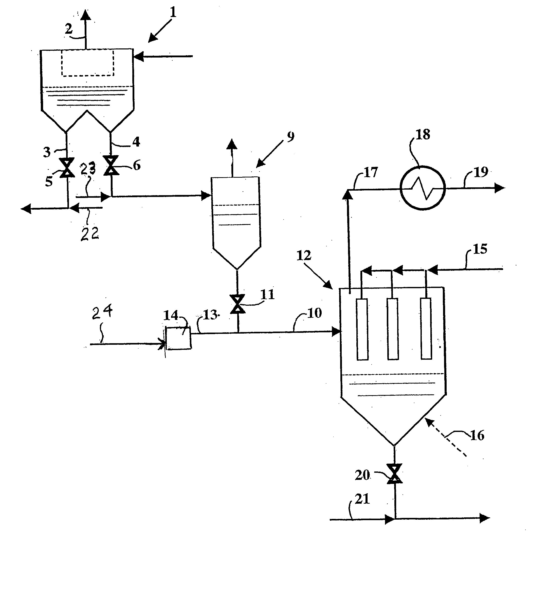
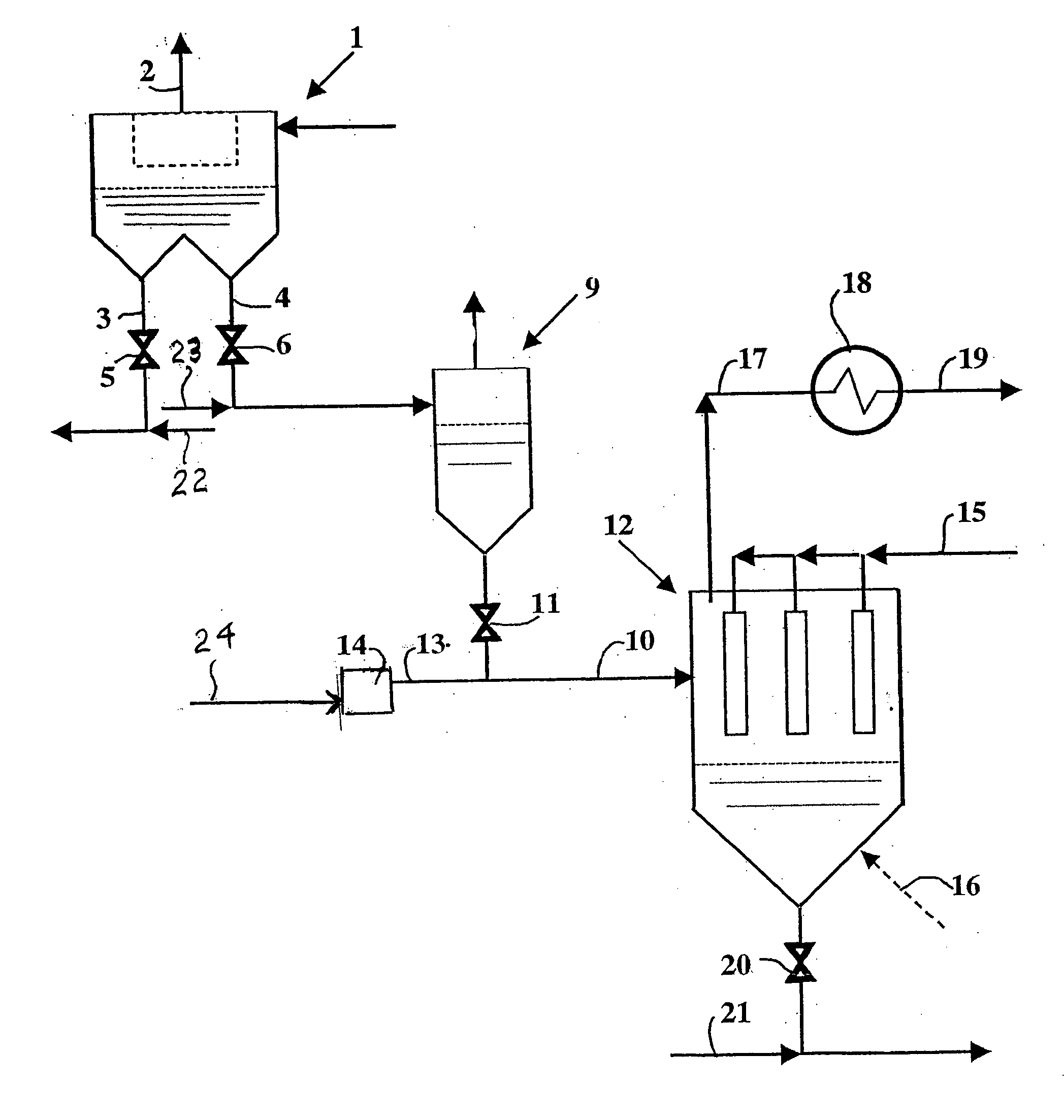
[0014] The present invention thus allows to minimize the number of equipments required for the regeneration stage by proposing partial combustion of the regeneration gas upstream from the regeneration process and by combining the regeneration reaction by means of a combustion means such as a burner for example, preferably located near to the absorbent regeneration and filtration zone. The proximity of the preheating means and of the regeneration / filtration zone also allows to limit handling and transport of corrosive fumes containing hydrogen sulfide for example.
[0016] Furthermore, the very nature of the regeneration gas allows to raise the conversion coefficient of the regeneration reaction, as explained hereafter.
[0017] Besides, no regeneration gas recycling is required, so that all the components linked with said recycling can be suppressed.

Problems solved by technology

However, supplying hydrogen to an industrial site, a refinery for example, can pose problems.
In fact, hydrogen is not always available in sufficient amount in refineries, in particular when substantial conversion and hydrodesulfurization operations are carried out.
Furthermore, the aforementioned two inventions, which allow regeneration of the absorbent, require specific equipments for the regeneration stage that are costly and numerous.

Method used


Image

  • Process and device intended for regeneration of used absorbents from thermal generator fumes treatment
  • Process and device intended for regeneration of used absorbents from thermal generator fumes treatment
  • Process and device intended for regeneration of used absorbents from thermal generator fumes treatment

Examples


Embodiment Construction

[0040] In this FIGURE, reference number 1 shows a dust separator allowing to filter the fumes of a boiler, of a furnace or of any thermal generator that specifically burns sulfur-containing liquid or gaseous fuels.

[0041] The outlet of such a boiler, as described in patent application FR-2,671,855, can thus constitute the inlet of filtering element 1. The outlet of any other means generating polluted effluents and equipped with the same fumes desulfurization means can of course constitute the inlet of element 1.

[0042] Dust separator 1, which is however not essential for the smooth running of the device according to the invention, allows a first separation of the fumes coming out of a stack 2 and the used absorbent having absorbed the sulfur oxides.

[0043] The used absorbent is thus discharged gravitationally from filtration means 1 through specific lines 3 and 4. Valves 5 and 6 or any other equivalent means placed on lines 3 and 4 can allow the used absorbent to be temporarily stor...


PUM

PropertyMeasurementUnit
temperaturesaaaaaaaaaa
temperatureaaaaaaaaaa

Abstract

Process and device for regeneration of a used absorbent from a desulfurization zone or from the desulfurization of a gas containing sulfur oxides, comprising regeneration simultaneously with filtering of the absorbent, in a reducing atmosphere, wherein partial combustion of a regeneration gas is also carried out upstream from regeneration, the products of the partial combustion being mixed with the used absorbent prior to the regeneration-filtration stage. The absorbent may be, e.g., solid absorbents based on magnesium oxide. The regeneration gas may be hydrogen sulfide and / or a hydrocarbon. For example, H2S can be partially combusted and the products of the partial combustion, including H2S, H2, SO2 and sulfur, mixed with the used absorbent prior to the regeneration-filtration stage.

Description

CROSS REFERENCE TO RELATED APPLICATION [0001] This application is a divisional application of U.S. Ser. No. 10 / 048,167, filed Apr. 18, 2002, the contents of which are incorporated by reference herein.FIELD OF THE INVENTION [0002] The present invention relates to the sphere of combustion and more particularly of regeneration of absorbents used for treatment of combustion products. BACKGROUND OF THE INVENTION [0003] French patent FR-2,636,720, filed by the applicant, discloses a boiler wherein desulfurization agents are injected into a specific zone, referred to as desulfurization chamber, interposed between the combustion chamber and the convective exchange heat recovery zone. The desulfurization agents used in this plant are preferably non-regeneratable calcic absorbents such as lime or limestone, or industrial residues with a high calcium carbonate content (sugar mill froth, paper mill froth, etc). [0004] Various improvements have been brought to this type of boilers in order to in...

Claims


Application Information

Patent Timeline
Patent Type & Authority Applications(United States)
IPC IPC(8): B01D53/50B01J20/34
CPCB01D53/508B01J20/041B01J20/3483B01J20/3458B01J20/3433B01D53/02B01D2257/302
Inventor LEBAS, ETIENNEMARTIN, GERARDSTREICHER, CHRISTIAN
Owner INST FR DU PETROLE
Learn More