
Ink for forming catalyst layer, and electrode and membrane-electrode assembly using the same

a technology of electrodes and electrode electrodes, applied in the direction of organic compounds/hydrides/coordination complexes, physical/chemical process catalysts, cell components, etc., can solve the problems of uneven distribution of polymer electrolyte, easy flooding, and reduce the gas diffusion property of electrodes, so as to prevent flooding, maintain high cell voltage for a long time with ease and reliability, and facilitate and reliable manufacture

Active Publication Date: 2005-03-24
PANASONIC CORP
View PDF2 Cites 16 Cited by
  • Summary
  • Abstract
  • Description
  • Claims
  • Application Information

AI Technical Summary

Benefits of technology

The present invention has been achieved in view of the above problems. An object of the present invention is to provide ink for forming a catalyst layer, which allows manufacture of a polymer electrolyte fuel cell comprising a catalyst layer having sufficient gas diffusion property and capable of preventing flooding and maintaining high cell voltage for a long time with ease and reliability. Another object of the present invention is to obtain a gas diffusion electrode and a membrane-electrode assembly which allow easy and reliable manufacture of a polymer electrolyte fuel cell capable of preventing flooding and maintaining high cell voltage for a long time. Still another object of the present invention is to obtain a polymer electrolyte fuel cell capable of preventing flooding and maintaining high cell voltage for a long time.

Problems solved by technology

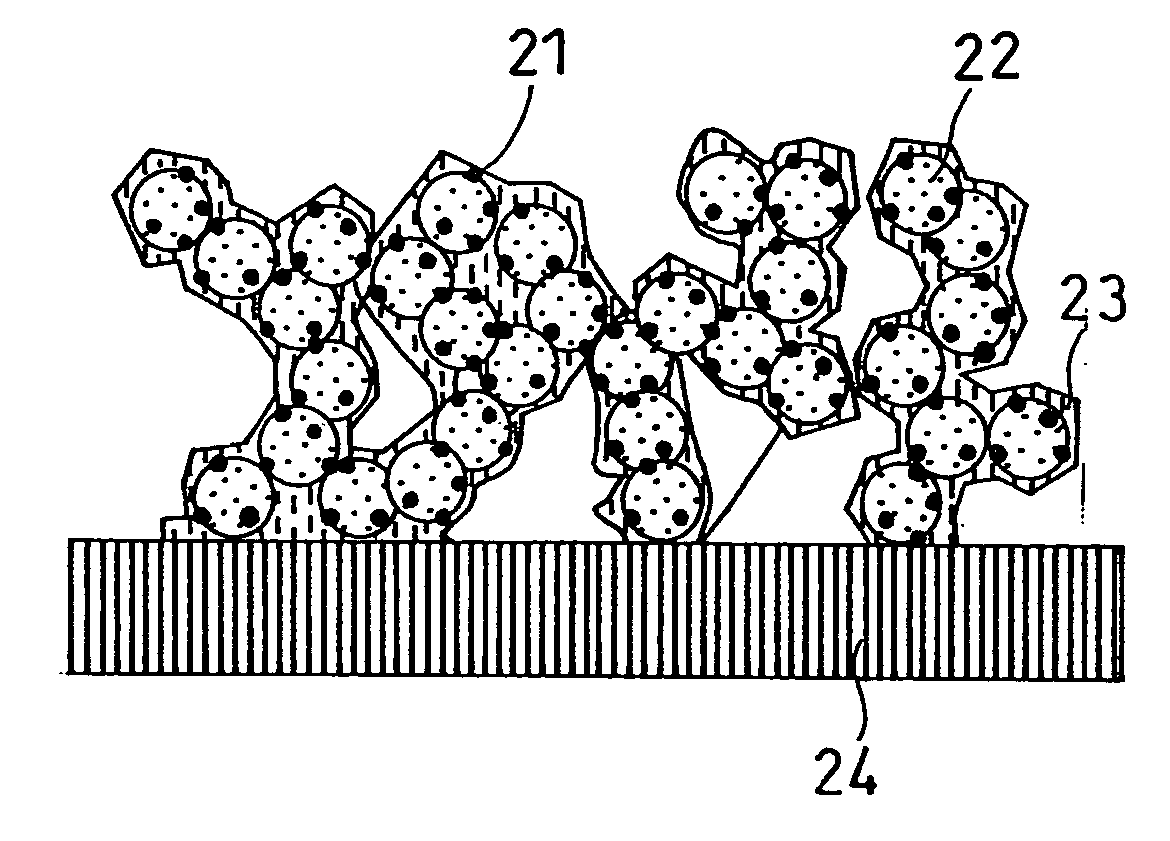
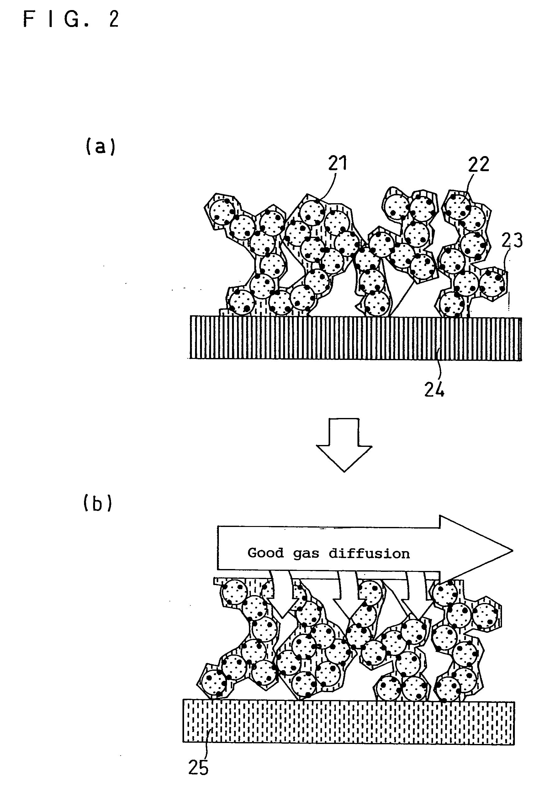
However, according to the prior art, the polymer electrolyte may remain in the gap in the catalyst layer through which gas should be supplied (gas supply channel) or the polymer electrolyte may distribute unevenly in the thickness direction of the catalyst layer made of the catalyst layer ink.
This may reduce the gas diffusion property of the electrode including the catalyst layer, causing easy occurrence of flooding.
In particular, regarding a fuel cell comprising the electrode including a catalyst layer in the above-described state, flooding may occur with time to reduce the voltage, even if the three-phase interface is favorably formed at the initial operation stage.
Therefore, the thus obtained electrode deteriorates in gas diffusion property and resistance to flooding.
Further, such a fuel cell causes voltage reduction due to flooding that occurs when the fuel cell is operated by high humidity reactant gases.

Method used


Image

  • Ink for forming catalyst layer, and electrode and membrane-electrode assembly using the same
  • Ink for forming catalyst layer, and electrode and membrane-electrode assembly using the same
  • Ink for forming catalyst layer, and electrode and membrane-electrode assembly using the same

Examples


examples 1-3

(a) Preparation of Catalyst Layer Ink

Catalyst-supporting particles comprising conductive carbon particles (mean particle diameter: 0.1 to 1.0 μm, TEC10E50E manufactured by Tanaka Kikinzoku Kogyo K. K.) and platinum as an electrode catalyst in the weight ratio of 1:1 were dispersed in a dispersion of a proton conductive polymer electrolyte in ethanol such that the weight ratio of the polymer electrolyte and the conductive carbon particles became 1:1. Thus, ink for forming a cathodic catalyst layer was obtained.

The polymer electrolyte concentration in the polymer electrolyte dispersion was 10 weight %. The proton conductive polymer electrolyte used was perfluorocarbonsulfonic acid (EW1100) having a mean inertia radius (2) in 100% ethanol and a molecular weight shown in columns A to C of Table 1.

Ink for forming an anodic catalyst layer was prepared in the same manner as the preparation of the cathode catalyst layer ink described above except that conductive carbon particles (mea...

examples

FIG. 7 indicates that the decreasing rate of the voltages of the comparative cells 1 and 2 increased with time, whereas the cells A to C maintained high voltages from the initial state for a long time. This indicates that the fuel cell using the catalyst layer of the present invention is able to maintain a stable voltage for a long time.

With use of the catalyst layer ink of the present invention, a polymer electrolyte fuel cell capable of maintaining high and stable voltage for a long time is provided. This fuel cell can suitably be adopted for motor vehicles and domestic cogeneration systems.


PUM

PropertyMeasurementUnit
Lengthaaaaaaaaaa
Pressureaaaaaaaaaa
Diameteraaaaaaaaaa

Abstract

The present invention provides ink for forming a catalyst layer containing at least a cation conductive polymer electrolyte, catalyst-supporting particles including conductive carbon particles and an electrode catalyst supported thereon, and a dispersion medium, wherein the polymer electrolyte has a mean inertia radius of 150 to 300 nm. A catalyst layer made of the catalyst layer ink improves in gas diffusion property and increases cell voltage, which allows providing a proton conductive polymer electrolyte fuel cell capable of maintaining the high cell voltage for a long time.

Description

BACKGROUND OF THE INVENTION The present invention relates to ink for forming a catalyst layer suitable for manufacturing a polymer electrolyte fuel cell. Further, the present invention relates to a gas diffusion electrode and a membrane-electrode assembly obtained using the ink, as well as a polymer electrolyte fuel cell comprising the gas diffusion electrode and the membrane-electrode assembly. A polymer electrolyte fuel cell is a device that causes an electrochemical reaction between a fuel gas and an oxidant gas, for example, between hydrogen and air, to generate electric power and heat simultaneously. FIG. 8 schematically illustrates a basic structure of such a polymer electrolyte fuel cell. In a fuel cell 2 shown in FIG. 8, catalyst layers 110a are formed on both surfaces of a cation (proton) conductive polymer electrolyte membrane 100 capable of selectively transporting cations (protons), respectively. Each of the catalyst layers 110a is closely adhered to the polymer elect...

Claims


Application Information

Patent Timeline
IPC IPC(8): B01J21/18B01J31/00H01M4/86H01M4/88H01M4/90H01M4/92H01M4/96H01M8/00H01M8/10
CPCH01M4/8605H01M4/881H01M4/8828H01M4/90Y02E60/522H01M4/926Y02E60/523Y02E60/50H01M4/921H01M4/86
Inventor SUGAWARA, YASUSHIMORITA, JUNJIYONAMINE, TAKESHITAKEBE, YASUO
Owner PANASONIC CORP
Learn More