Imaging device and manufacturing method thereof

a technology of imaging device and manufacturing method, which is applied in the direction of color television, television system, radio control device, etc., can solve the problems of not discovering a method for realizing such a structure, prone to overflow of electrons accumulated in the photodiode, and prone to turning the channel of the transfer gate, so as to reduce the leakage of junctions, deepen the potential of floating diffusion region, and prolong the standby time

Active Publication Date: 2005-03-31
FUJITSU SEMICON LTD
View PDF7 Cites 80 Cited by
  • Summary
  • Abstract
  • Description
  • Claims
  • Application Information

AI Technical Summary

Benefits of technology

According to the above-described first aspect of the present invention, an opposite area of the transfer gate and the floating diffusion region can be made large by the transfer gate having concave or convex portion, and an overlap capacitance between the transfer gate and the floating diffusion region can be increased. Hence, when a predetermined potential is applied to the transfer gate to turn on a channel under the transfer gate, a potential of the floating diffusion region is drawn to a potential of the transfer gate to be deepened by the above-described overlap capacitance, and charges generated in the photodiode can be efficiently transferred to the floating diffusion region.
In this case, the angled ion-implantation is performed while tilting the semiconductor substrate to a direction where the impurity is implanted under the first side face of the transfer gate, and thus the impurity is implanted under the transfer gate. Accordingly, the highly doped region can be overlapped with the transfer gate before the impurity is diffused. Hence, when the impurity is diffused by a heat treatment process, the highly doped region overlaps the transfer gate largely in comparison with the fourth aspect of the present invention, and accordingly, the overlap capacitance between the highly doped region and the transfer gate is made further larger, and the charge transfer efficiency can be further enhanced.

Problems solved by technology

However, Patent Document 1 described above does not go beyond disclosing the structure of extending the transfer gate onto the floating diffusion region, and does not discover a method for realizing such a structure.
Therefore, the channel of the transfer gate becomes prone to be turned on, and the electrons accumulated in the photodiode become prone to overflow to the floating diffusion region through the transfer gate.
Accordingly, a ratio (S / N ratio) of the signal voltage value and a noise voltage value becomes reduced, causing a possibility that noise of the imaging device is increased.

Method used


Image

  • Imaging device and manufacturing method thereof
  • Imaging device and manufacturing method thereof
  • Imaging device and manufacturing method thereof

Examples


first embodiment

(First Embodiment)

First, an imaging device according to a first embodiment of the present invention will be described.

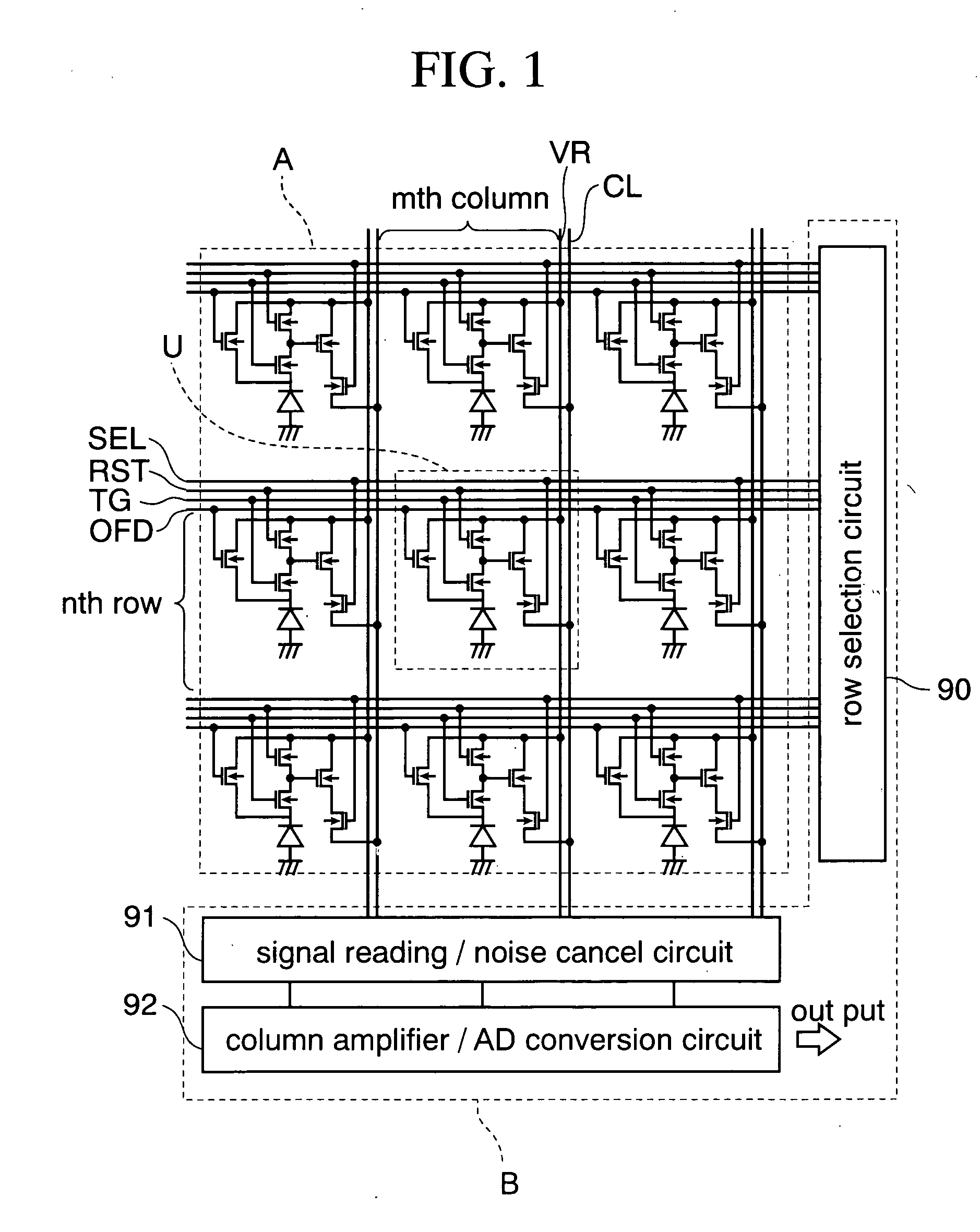
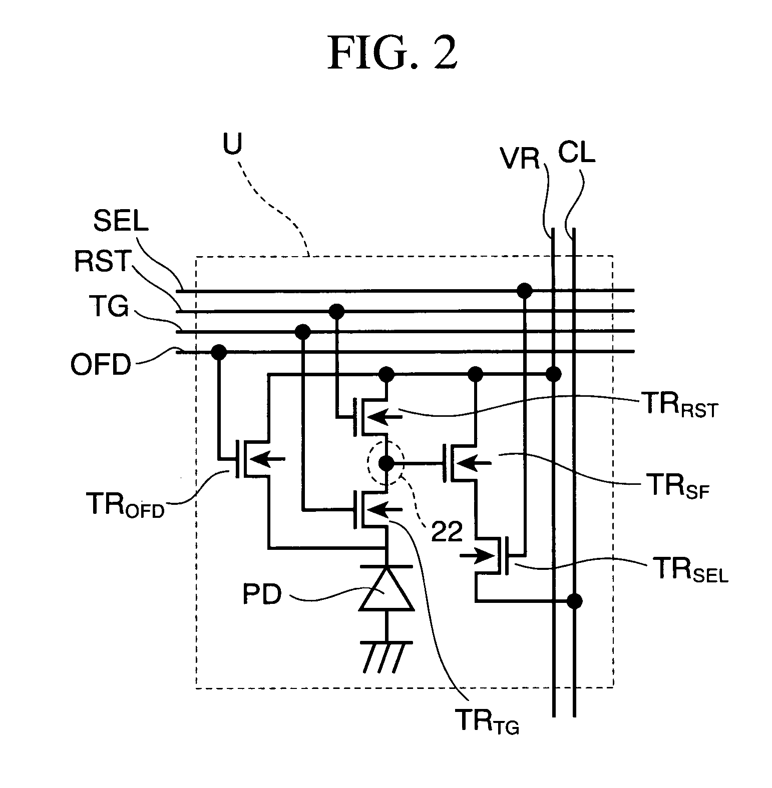
FIG. 1 is a circuit diagram of the imaging device according to this embodiment.

This imaging device is a CMOS image sensor, and can take both of a moving picture and a static image.

As shown in FIG. 1, this image sensor is broadly divided into a pixel region A and a peripheral circuit region B when viewed from the above. a plurality of unit pixels U are repeatedly arrayed in row and column directions on the pixel region A.

On the other hand, a row selection circuit 90, a signal reading / noise cancel circuit 91, and a column amplifier / AD conversion circuit 92 are formed on the peripheral circuit region B, as shown in the figure. Row selection line SEL, reset line RST, transfer gate line TG, and overflow drain line OFD, which is common to the unit pixels U in one row, is electrically connected to the row selection circuit 90. A vertical signal line CL, which is com...

second embodiment

(Second Embodiment)

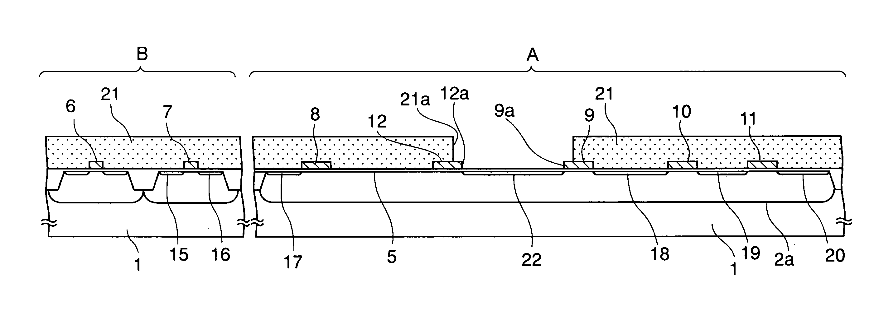
Next, a second embodiment of the present invention will be explained with reference to FIG. 4C and FIG. 15. FIG. 15 is a cross-sectional view of principal portions of an imaging device at some midpoint of a manufacturing process according to the present embodiment.

In the first embodiment, the ion implantation is performed twice by use of the two resist patterns (second and third resist patterns 21 and 23), thus forming the floating diffusion region 22 including the highly doped region 22a.

On the contrary to this, the highly doped region 22a is formed by following method in this embodiment.

First, performing the process of FIG. 4C, which is described in the first embodiment, the floating diffusion region 22 is formed by use of a first resist pattern 21 with a thickness of approximately 1 μm.

Subsequently, as shown in FIG. 15, while tilting the silicon substrate 1 to such a direction where a shadow of the first resist pattern 21 is extended from the second si...

third embodiment

(Third Embodiment)

In this embodiment, a modification example of the plane layout of the transfer gate 12 described in the first embodiment will be explained.

FIG. 17 is a plan view of principal portions of an imaging device according to the present embodiment. In FIG. 17, the same reference numerals are used for the members described in the first embodiment.

As shown in FIG. 17, in this embodiment, an extending portion 12c extending along the edge of the floating diffusion region 22 when viewed from above the silicon substrate 1 is provided in the transfer gate 12. According to this structure, the opposite area of the transfer gate 12 and floating diffusion region 22 can be widened more in comparison with the first embodiment, and the overlap capacitance therebetween is further increased. Therefore, the charge transfer efficiency from the photodiode PD to the floating diffusion region 22 can be further enhanced.

Note that, if the overlap capacitance between the transfer gate 12 a...


PUM


Abstract

Disclosed is an imaging device including a photodiode and floating diffusion region formed to be spaced from each other on a surface layer of a pixel region of a silicon (semiconductor) substrate, and a transfer gate having one of a concave and convex portions toward the floating diffusion region, the transfer gate being formed above the silicon substrate between the photodiode and the floating diffusion region by interposing a gate insulating film therebetween.

Description

CROSS-REFERENCE TO RELATED APPLICATIONS This application is based on and claims priority of Japanese Patent Application No. 2003-335484 filed on Sep. 26, 2003, the entire contents of which are incorporated herein by reference. BACKGROUND OF THE INVENTION 1. Field of the Invention The present invention relates to an imaging device and a manufacturing method thereof. More specifically, the present invention relates to a CMOS imaging device capable of performing charge transfer efficiently and to a manufacturing method thereof. 2. Description of the Related Art In recent years, mobile devices such as cellular phones have kept becoming more and more multifunctional. Among other things, a camera phone capable of easily taking a moving picture and a static image has been widespread, due to reflection of user's interests. It is necessary for such a mobile device to save power so as to be durable for long-time use. Moreover, as for a camera (hereinafter, referred to as an imaging eleme...

Claims


Application Information

Patent Timeline
Patent Type & Authority Applications(United States)
IPC IPC(8): H01L27/146H01L27/148H04N5/335H04N5/357H04N5/369H04N5/374H04N5/376
CPCH01L27/14601H01L27/14603H01L27/14609H01L27/14689H01L27/14632H01L27/14636H01L27/14618H01L2924/0002H01L2924/00
Inventor OHKAWA, NARUMI
Owner FUJITSU SEMICON LTD
Why Eureka
Try Eureka