Motor driver

a motor and driver technology, applied in the direction of dynamo-electric converter control, dynamo-electric gear control, instruments, etc., can solve the problems of long time, deterioration of the insulation of the motor, and long operation time of the apparatus

Active Publication Date: 2005-03-31
FANUC LTD
View PDF4 Cites 17 Cited by
  • Summary
  • Abstract
  • Description
  • Claims
  • Application Information

AI Technical Summary

Benefits of technology

[0020] According to the present invention, as the motor driver with the above configuration rectifies the voltage from the AC power supply to store it in the capacitor and uses the stored power as the power supply for measuring the insulation resistance of the motor, motor insulation resistance to ground can be measured and the insulation deterioration can be detected for any types of AC power supply used in a motor driver, regardless of how the AC power supply is grounded.

Problems solved by technology

Over many years of use, the insulation of a motor deteriorates depending on the environment in which the motor is used and other conditions.
If current leaks due to insulation deterioration, a leakage current circuit breaker operates and abruptly stops the operation of the apparatus using the motor.
In this case, it takes long time to find the cause of such abrupt stop, as it is unknown whether the problem derives from the motor or the motor driver, with the result that the interruption of the apparatus or production line using the motor tends to extend for a long period of time.
Conventional devices for detecting leakage current, such as leakage current detectors and leakage current protection relays, have the drawback of being unable to detect leakage current until insulation deterioration is in an advanced stage, because the detection threshold is normally approximately 15 mA in small detectors, and approximately 3 mA in the smallest detectors.
Another drawback of conventional leakage current detectors is that when an apparatus or production line suddenly stops due to leakage current, the entire system operation of the apparatus or production line has to be stopped to investigate whether the problem derives from the motor itself, the motor driver, or a peripheral device.
A further drawback of conventional leakage current detection devices is that they are not useful for predicting insulation deterioration for preventive maintenance of the motor.
Detectors for this purpose must allow for high current, which becomes a cost-raising factor.
In the motor driver proposed in this Japanese patent application, the voltage applied for detection of insulation resistance becomes a three-phase half-wave rectified voltage in the case of a neutral grounded AC power supply, while it becomes a three-phase half-wave rectified voltage in which one phase out of three phases lacks in the case of a single-line grounded AC power supply, which leads to generation of pulse-shaped voltage, causing a trouble.
If the motor insulation resistance lowers, the potential difference across the detection resistance lowers, with the result that the motor insulation deterioration is detectable.
In the case of single-line grounded AC power supply, however, the applied voltage is pulse-shaped and is affected by a parasitic capacitance which exists together with, and in parallel with, the motor insulation resistance.
It is difficult, however, to change the values of the detection resistor and reference voltage, because the value of the capacitance CM is unknown.

Method used


Image

  • Motor driver
  • Motor driver
  • Motor driver

Examples


Embodiment Construction

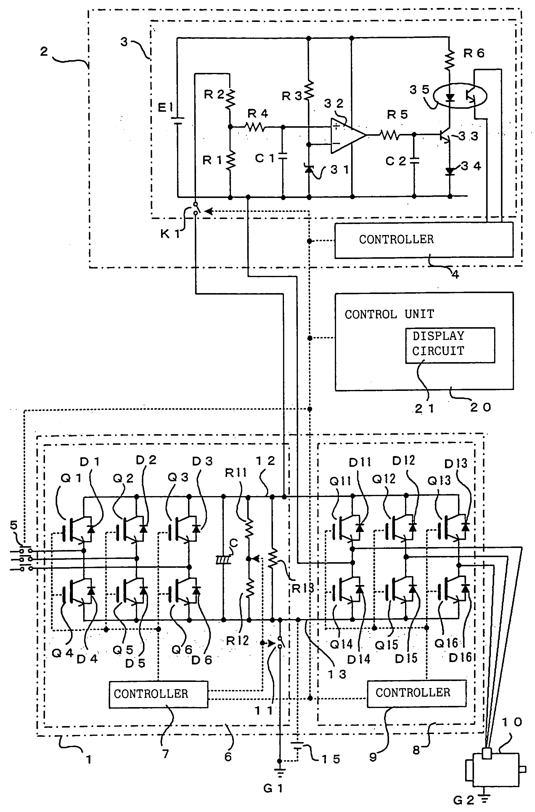
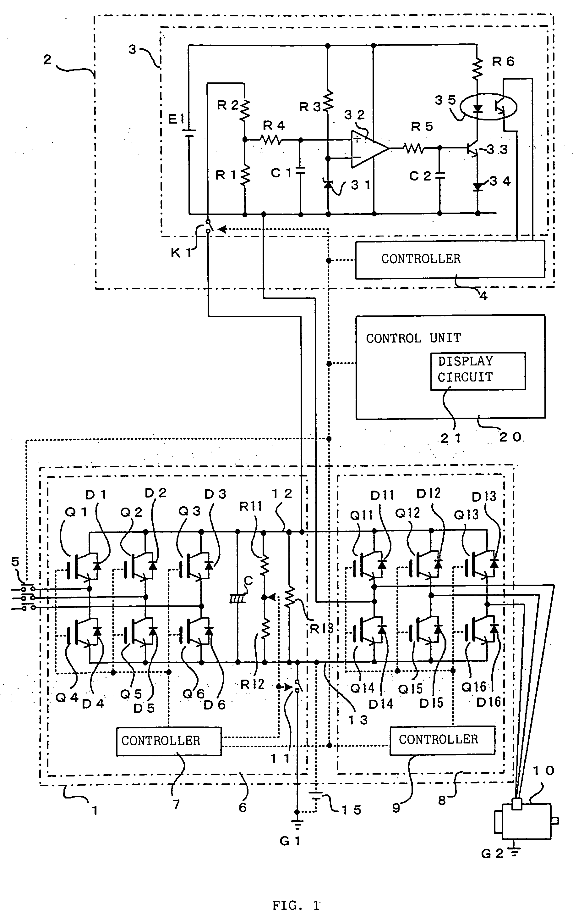
[0027]FIG. 1 is a block circuit diagram illustrating essential components of the motor driver according to a first embodiment of the present invention. As shown in FIG. 1, the motor driver unit 1 consists of a power supply section 6 including a rectifier circuit for converting a three-phase AC power supply to a DC power supply; and a motor drive amplifier 8 for inverting the DC power supply to the AC power supply required for driving a motor 10. In the present invention, a motor insulation resistance detector 2 is added to the motor driver unit 1. The motor insulation resistance detector 2 consists of a voltage detection circuit 3 and a controller 4.

[0028] The power supply section 6 in the motor driver unit 1 includes a rectifier circuit comprising diodes D1 to D6 for rectifying and converting power supplied through electromagnetic switch contacts 5 from a three-phase AC power supply to a DC power supply; and switching elements Q1 to Q6, each of which is an IGBT or the like, connec...


PUM


Abstract

While the motor drive amplifier is not operating, electromagnetic switch contacts are held closed for a predetermined period of time, three-phase power is rectified by a rectifier circuit and a smoothing capacitor is charged. Then, the smoothing capacitor is discharged through a discharging resistor and, when a predetermined voltage is reached, a contact is closed, with the result that a closed circuit is formed by the smoothing capacitor, a detection resistor, a motor coil, motor insulation resistance, and ground. A voltage generating across the detection resistor due to leakage current is detected and compared with a reference value. If the detected voltage exceeds the reference value, an insulation degradation signal is delivered.

Description

BACKGROUND OF THE INVENTION [0001] 1. Field of the Invention [0002] The present invention relates to a motor driver capable of detecting motor insulation deterioration. [0003] 2. Description of the Related Art [0004] Over many years of use, the insulation of a motor deteriorates depending on the environment in which the motor is used and other conditions. If current leaks due to insulation deterioration, a leakage current circuit breaker operates and abruptly stops the operation of the apparatus using the motor. In this case, it takes long time to find the cause of such abrupt stop, as it is unknown whether the problem derives from the motor or the motor driver, with the result that the interruption of the apparatus or production line using the motor tends to extend for a long period of time. [0005] Motor insulation deterioration is generally detected by detecting the leakage current, as described above. Conventional devices for detecting leakage current, such as leakage current det...

Claims


Application Information

Patent Timeline
Patent Type & Authority Applications(United States)
IPC IPC(8): G01R31/12G01R31/02G01R31/34H02K11/00H02P27/06H02P27/08
CPCH02P27/08G01R31/343
Inventor YAMADA, YUUICHIOTA, NAOTOHARADA, TAKASHIYAESHIMA, MAMORU
Owner FANUC LTD
Why Eureka
Try Eureka