Power supply system

a power supply system and power supply technology, applied in fixed transformers, transportation and packaging, liquid/fluent solid measurement, etc., can solve the problems of no compatibility among ac adapters, and flood of houses with many ac adapters, so as to save space

Inactive Publication Date: 2005-03-31
SHARP KK
View PDF5 Cites 414 Cited by
  • Summary
  • Abstract
  • Description
  • Claims
  • Application Information

AI Technical Summary

Benefits of technology

[0016] In light of the above problems, it is an object of the present invention to provide a power supply system capable of not only supplying power to different types of electronic equipment by using a single power transmission apparatus, but also saving space and performing payment for public service and charges.

Problems solved by technology

This means that there is no compatibility among AC adapters.
Especially, in the case of the portable telephone, dedicated AC adapters are used for respective portable telephones which are different in model or make, thereby providing no compatibility among these AC adapters, only being resulted in inconvenience.
Since there is no compatibility among AC adapters, a problem has arisen that a house is flooded with many AC adapters.
In a case where many adapters are present in a house, another problem has arisen that the AC adapters and cords used for connecting the AC adapters to the commercial power supply become impediments to movement of family members.
In a case where equipment is installed on a shelve, such as a personal computer rack, relocating the equipment involves both the equipment and an AC adapter thereof as a set, only resulting in cumbersomeness.
An AC adapter specially designed for corresponding electronic equipment is necessary to be carried by a person who carries the electronic equipment in a public facility at a destination of travel or in transit, which has greatly devalued portability of the mobile electronic equipment.
When an automobile is used for traveling, a charging adapter is attached to a dashboard, a console box, or the like to thereby charge a portable telephone, whereas in such a case, the adapter and a cord thereof become obstacles during driving, and a case arose where a view field of a driver is partly blocked.
However, only one designated type of electronic equipment can be charged by the non-contact charger with a problem that the non-contact charger cannot charge plural types of electronic equipment.
In such situations, the cashier or the front desk is crowded, causing a problem of disabling a smooth payment.
In a case where a train ticket is purchased from an automatic ticket dispenser, it is necessary to find out a fare to a destination in a fare schedule or the like and then purchase the ticket, which has been problematically cumbersome.
In addition, another annoyance accompanies when the ticket is actually purchased, small change has to be carried.
On the other hand, there is a payment method already available in which a prepaid card is purchased in advance, and the prepaid card is put through an automatic ticket dispenser installed at a ticket gate in a station, and thereby a charge required for a boarding distance is subtracted from a recorded balance on the prepaid card, whereas a problem has remained unsolved that such a prepaid card is not standardized among railway companies.

Method used


Image

  • Power supply system
  • Power supply system
  • Power supply system

Examples


first embodiment

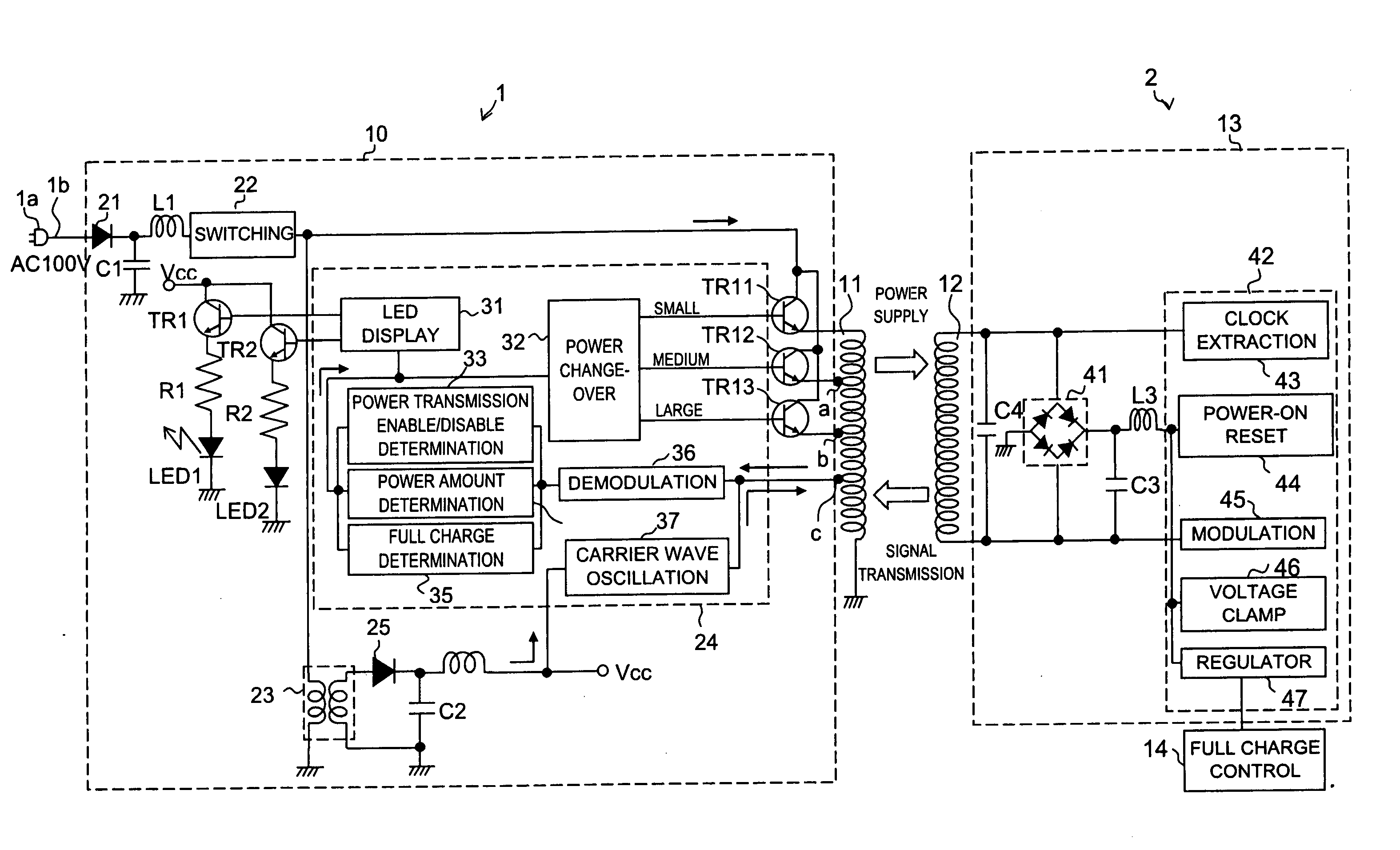
[0067]FIG. 3 is a block diagram showing an electric configuration of a power supply system of the present invention. In FIG. 3, the same constituents as in FIGS. 1A, 2A, and 2B are attached with the same symbols and descriptions thereof will not be given herein.

[0068] In FIG. 3, a commercial power supply (AC 100 V) is externally fed from the AC plug 1a through the cord 1b, and the supplied AC 100 V is full-wave rectified in a rectification circuit 21 in the primary side circuit 10 and thereafter smoothed in a smoothing circuit constituted of a coil L1 and a capacitor C1 so as to be converted into a DC voltage. A pulse voltage obtained by subjecting the DC voltage to switching in a switching circuit 22 is supplied to the primary side coil 11 through transistors (power change-over section) TR11, TR12, and TR13.

[0069] All of the transistors TR11, TR12, and T13 are NPN-type transistors, and collectors thereof are all connected to an output terminal of the switching circuit 22. An emitt...

second embodiment

[0090]FIG. 5 is a block diagram showing an electric configuration of a power supply system of the present invention. In FIG. 5, the same constituents as in FIG. 3 are attached with the same symbols and descriptions thereof will not be given herein. The power supply system shown in FIG. 5 is different from the power supply system shown in FIG. 3 in that a primary side coils 11x, 11y, and 11z are provided instead of the primary side coil 11 of the power transmission apparatus 1. The three primary side coils are attached with the symbols 11x, 11y, and 11z in the descending order of the number of turns thereof, and one ends thereof are all grounded. Other end of the primary side coil 11x is connected to the emitter of the transistor TR11; other end of the primary side coil 11y is connected to the emitter of the transistor TR12; and other end of the primary side coil 11z is connected to the emitter of the transistor TR13. The coils are provided with a tap d (on the primary side coil 11x)...

third embodiment

[0093]FIG. 6 is a block diagram showing an electric configuration of a power supply system of the present invention. In FIG. 6, the same constituents as in FIG. 3 are attached with the same symbols and descriptions thereof will not be given herein. The power supply system shown in FIG. 6 is different from the power supply system shown in FIG. 3 in that primary side coils 11a and 11b are provided instead of the primary side coil 11 of the power transmission apparatus 1, and secondary side coils 12a and 12b are provided instead of the secondary side coil 12 of the portable telephone 2.

[0094] In the power transmission apparatus 1 shown in FIG. 3, the demodulation circuit 36 and the carrier wave oscillation circuit 37 are connected to the tap c of the primary side coil 11. However, in the power transmission apparatus 1 shown in FIG. 6, the demodulation circuit 36 and the carrier wave oscillation circuit 37 are connected to one end of the primary side coil 11b, and the other end of the p...


PUM


Abstract

A power supply system according to the present invention comprises: a primary side coil; a power transmission apparatus having a primary side circuit for feeding a pulse voltage resulted from switching a DC voltage which is obtained by rectifying and smoothing a commercial power supply to the primary side coil; a secondary side coil magnetically coupled to the primary side coil; and power reception equipment having a secondary side circuit for rectifying and smoothing voltage induced across the secondary side coil, wherein there is provided a power adjusting section for adjusting a level of power to be transmitted according to power required by the power reception equipment. The power adjusting section has, in the primary side circuit, a carrier wave oscillation circuit for supplying a carrier wave to the primary side coil, a demodulation circuit for demodulating a modulated signal transmitted from the secondary circuit and received by the primary side coil, and a power change-over section for selecting a level of power to be transmitted according to an information signal from the power reception equipment and demodulated by the demodulation circuit. The power adjusting section has, in the secondary side circuit, a modulation circuit for modulating the carrier wave fed from the carrier wave oscillation circuit and received by the secondary side coil with the information signal from the power reception equipment and transmitting the modulated signal.

Description

[0001] This non-provisional application claims priorities under 35 U.S.C. §119(a) on Patent Application No. 2003-340631 filed in Japan on Sep. 30, 2003, Patent Application No. 2003-340772 filed in Japan on Sep. 30, 2003, and Patent Application No. 2003-341350 filed in Japan on Sep. 30, 2003, the entire contents of which are hereby incorporated by reference. BACKGROUND OF THE INVENTION [0002] 1. Field of the Invention [0003] The present invention relates to a power supply system that supplies power to electronic equipment and, more particularly, to a power supply system that supplies power to mobile electronic equipment such as portable telephones, notebook personal computers, a digital cameras, and an electronic toys. [0004] 2. Description of the Prior Art [0005] In FIGS. 27 to 29, there are shown examples of a conventional power supply system that supplies power to mobile electronic equipment. FIG. 27 is a view showing an outer appearance of a conventional power supply system perfo...

Claims


Application Information

Patent Timeline
Patent Type & Authority Applications(United States)
IPC IPC(8): G06F1/26H02J5/00H02J7/00H02J7/02
CPCG06F1/26H02J7/025H02J7/0068H02J5/005H02J50/80H02J50/10H02J7/0049H02J50/90H02J50/40H02J50/60
Inventor NAKAMURA, JUNICHIKAWAMURA, MASAHIROOKADA, YUTAKAMORIMOTO, TAKESHI
Owner SHARP KK
Why Eureka
Try Eureka