Device and method for investigating analytes in liquid suspension or solution

a liquid suspension and analyte technology, applied in the field of devices and methods for investigating analytes in liquid suspension or solution, can solve the problems of limiting the number of fluorescent wavelengths that are typically used in commercial applications today, bulky and expensive, and limiting their broad use in research and clinical practice, so as to achieve easy adaptation to different investigations and expand the possibilities of application

Inactive Publication Date: 2005-03-31
PROIMMUNE
View PDF5 Cites 56 Cited by
  • Summary
  • Abstract
  • Description
  • Claims
  • Application Information

AI Technical Summary

Benefits of technology

[0013] It is an object of the present invention to provide an optical detection device for analysing analytes in a liquid suspension or solution that can be scaled to detect and process a large number of wavelengths of incident and fluorescent light simultaneously, which is small in size and can be easily adapted to different investigation requirements to enlarge the possibilities of its application.
[0021] Preferably, doped absorbing regions may be provided on the first substrate adjacent to the analyte channel and the waveguide(s) for reducing the amount of unguided light propagating in the first substrate.
[0027] An analyte sorting means designed in this way enables the separation of analytes even of very small sample amounts.
[0055] By designing a device for analysing analytes in a liquid suspension or solution according to the present invention a very compact and high channel count system can be realised cost-effectively. This allows saving valuable bench-space in laboratory or point-of-care applications, or even the realisation of a hand-held device. The optical detection device can be manufactured, to a large extent with high-volume semiconductor processing technologies like lithographic patterning, masking and etch processes or the like, which allow for the realisation of very high specification and narrow tolerance devices in high volumes and at low cost. The possibility of arranging the different sections of the optical detection device and the discrete components of these sections independently from one another on the substrates permits an assembly of the device, that can be optimised according to certain requirements, e.g. of the analytes, the light source or the components. The present invention will therefore enable use of a described flow-cytometric and similar industrial and / or biomedical analyte detection and handling applications in new areas of medical and scientific use.
[0056] By integrating the channel and the waveguides on the surface of a planar substrate the total amount of space required by the optical detection device can be reduced substantially.

Problems solved by technology

Because of the size of the individual components in the detection subsystem it is challenging to manage the spatial arrangement of all optical components when a system with a relatively large number of detectors is required.
These constraints tend to limit the number of fluorescent wavelengths that are typically used in commercial applications today.
At the same time they are bulky and expensive limiting their broad use in research and clinical practice.
Cell sorters that detect a larger number of colours have been designed, but are not used in wide practice.
This is mainly due to the fact that extending the existing bulk optical and fluidics technologies to higher numbers of colours that can be discriminated is very expensive and cumbersome.

Method used


Image

  • Device and method for investigating analytes in liquid suspension or solution
  • Device and method for investigating analytes in liquid suspension or solution
  • Device and method for investigating analytes in liquid suspension or solution

Examples


Embodiment Construction

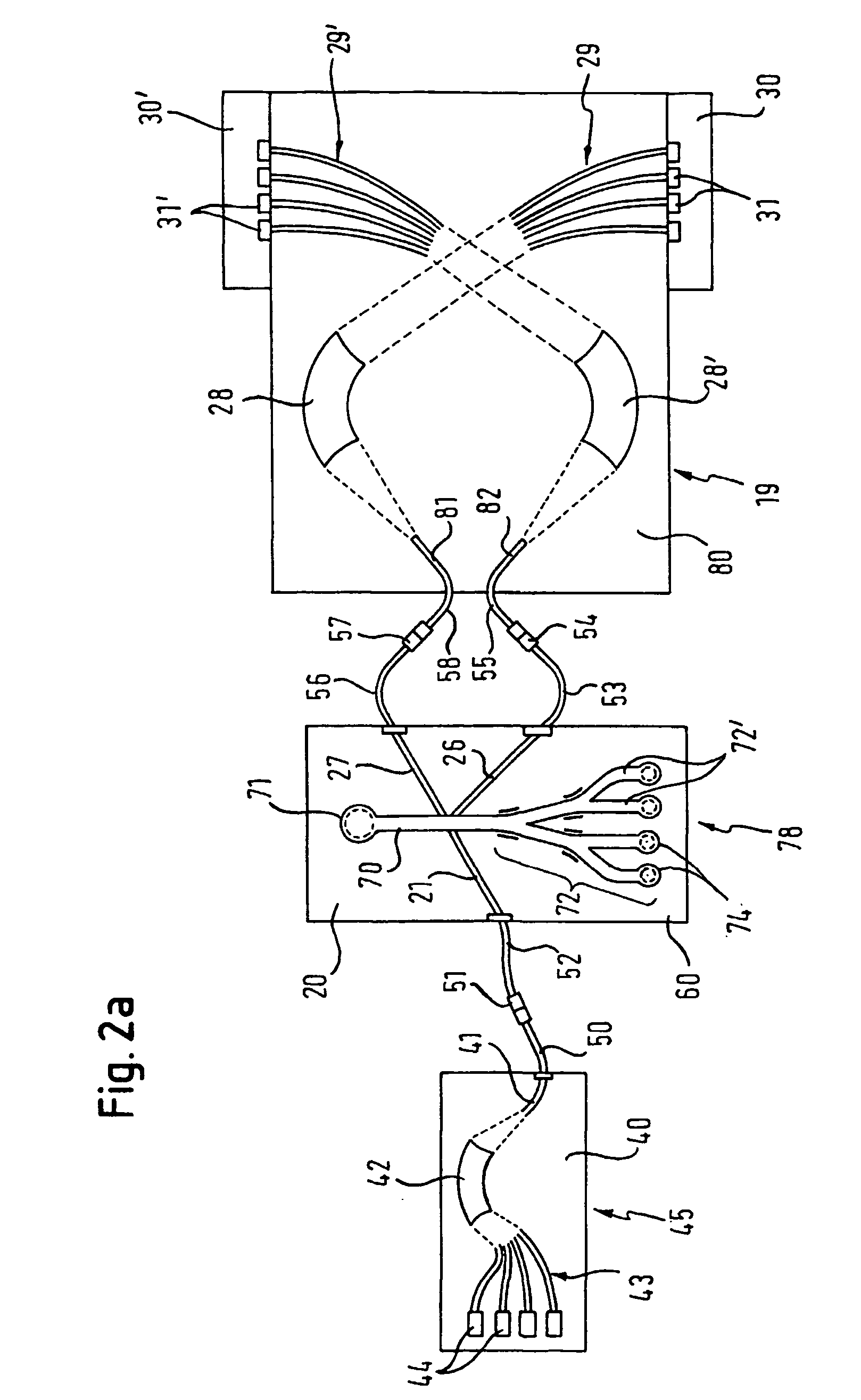
[0072] In FIG. 2a an embodiment of an optical detection device according to the present invention is shown, which comprises a light supplying means 45 integrated on a planar substrate device 40, an analyte handling means 78 integrated on a planar substrate device 20, a light directing means 19 integrated on a planar substrate device 80, and detection means integrated on planar substrate devices 30, 30′. Also shown is a plurality of optical waveguides, which are integrated in the substrate devices and are designed to direct light emitted by the light supplying means 45 through the different sections of the optical detection device to the detection means. In the analyte handling means 78 there is shown an analyte channel 70 for the liquid flow of the analyte suspension or solution and an analyte sorting means 72 comprising several sorting channels 72′ for different properties of the analytes.

[0073] The planar substrate devices 20, 40, 80 may for example be a silica or silica on silic...


PUM

PropertyMeasurementUnit
angleaaaaaaaaaa
angleaaaaaaaaaa
angleaaaaaaaaaa

Abstract

An optical detection device is provided for analysing analytes in a liquid suspension or solution that can detect and process a large number of wavelengths of incident and fluorescent light simultaneously, which is small in size and can be easily adapted to different investigation requirements. In one embodiment an optical detection device comprises a light supplying means (45), an analyte handling means (78), a light directing means (19), and detection means, integrated on planar substrate devices (40), (20), and (30), (30′), respectively. A plurality of optical waveguides are integrated in the substrate devices to direct light emitted by the light supplying means (45) through the different sections of the optical detection device to the detection means. The analyte handling means (78) comprises an analyte channel (70) for the liquid flow of the analyte suspension or solution and an analyte sorting means (72) comprising several sorting channels (72′).

Description

FIELD OF THE INVENTION [0001] The present invention relates to a device and a method for investigating analytes in liquid suspension or solution. BACKGROUND OF THE INVENTION [0002] Flow cytometry is a well-known fluorescent analysis technique, which can, for example, be used to detect and separate blood cells in a suspension according to their phenotypic properties. This can be achieved by staining the cells in the sample to be analysed for example with a monoclonal antibody specific to a phenotypic marker, which itself is coupled to a fluorescent dye. Different phenotypic cell surface markers can therefore be distinguished when dyes with different fluorescent wavelengths, e.g. green and red, are coupled to a number of different antibodies, each specific to a different marker. [0003] To perform this analysis technique a Fluorescence Activated Cell Sorter, generally called FACS, is known, which is a complex device comprising optical and fluid-handling subsystems, which are usually as...

Claims


Application Information

Patent Timeline
Patent Type & Authority Applications(United States)
IPC IPC(8): B01L3/00C12M1/00C12M1/26C12M1/34G01N15/14G01N21/64G01N33/49G01N37/00
CPCB01L3/502715B01L3/502776B01L2200/0636G01N21/53G01N15/1459G01N21/645G01N2015/149B01L2300/0654G01N15/14G01N21/6428G01N2021/6439
Inventor SCHWABE, NIKOLAI FRANZ GREGOR
Owner PROIMMUNE
Why Eureka
Try Eureka