Laser triangulation of the femoral head for total knee arthroplasty alignment instruments and surgical method

a technology of femoral head and total knee arthroplasty, which is applied in the field of laser triangulation of femoral head for total knee arthroplasty alignment instruments and surgical methods, can solve the problems of rapid failure of implants, limited discussion, and rapid failure, and achieve the effect of improving the accuracy of resection

Inactive Publication Date: 2005-03-31
PETERSEN THOMAS D
View PDF3 Cites 204 Cited by
  • Summary
  • Abstract
  • Description
  • Claims
  • Application Information

AI Technical Summary

Benefits of technology

It is a yet further object of the present invention to provide such a device in which a laser beam is used to dramatically enhance the accuracy of the resections that must be carried out during the performance of total knee surgery.

Problems solved by technology

It has been proven that only 4.5 degrees of misalignment causes the components to only load one side of the knee joint leading to rapid failure of the implant.
Misaligned total knee arthroplasties tend to get worse with time because the abnormal weight distribution accelerates the wear on the overloaded side leading to rapid failure within a few years in the case of the grossly malaligned.
Consequently, this discussion will be limited to the distal femoral cut, which is blind to the surgeon because the femoral head location cannot easily be determined.
There are three problems with this system.
The first is that it requires a rigid fixation system of the resection head to the distal femur because a substantial force is necessary to rotate the cutting head to the center of rotation.
The second problem is that the system requires the patient's entire leg be suspended freely so no external restrictions will affect the subsequent traction procedure.
The elaborate suspension system is expensive and time consuming to set up.
The third problem is that the surgeon has no way to check the accuracy of the traction procedure and has to proceed on faith that the system is accurate.
If the X-ray beam is not exactly perpendicular to the patient's hip, there is parallax error showing up on the X-ray as to the location of the femoral head.
The problems with this system include the elaborate X-ray system that requires proper positioning of the patient on the custom X-ray cassette and the time it takes to set up, take and interpret the X-ray.
Although everything has been done to eliminate parallax error, the patient's femur is only roughly equidistant between the radiographic scales so there is still residual inherent error present in the system, albeit only more than one degree in 10 percent of patients.
There are three major problems with intramedullary alignment systems.
The first is an inherent spatial mechanical error of up to 2-3 degrees in both saggital and axial alignment because the intramedullary canal has a cross-section about the size of a nickel.
The second major problem is, not infrequently, the femur is deformed so that it cannot provide a reliable guide.
Lastly, there are well-documented medical complications when the intramedullary system is used that are not present with the extramedullary approach.
Fat embolism can be a serious problem.
The intramedullary fat, dislodged by the drilling and placement of the rod, gets into the patient's blood stream and in most cases causes lethargy and sensorial changes that inhibit the patient's post-operation rehabilitation and delay hospital discharge at least one day.

Method used


Image

  • Laser triangulation of the femoral head for total knee arthroplasty alignment instruments and surgical method
  • Laser triangulation of the femoral head for total knee arthroplasty alignment instruments and surgical method
  • Laser triangulation of the femoral head for total knee arthroplasty alignment instruments and surgical method

Examples


Embodiment Construction

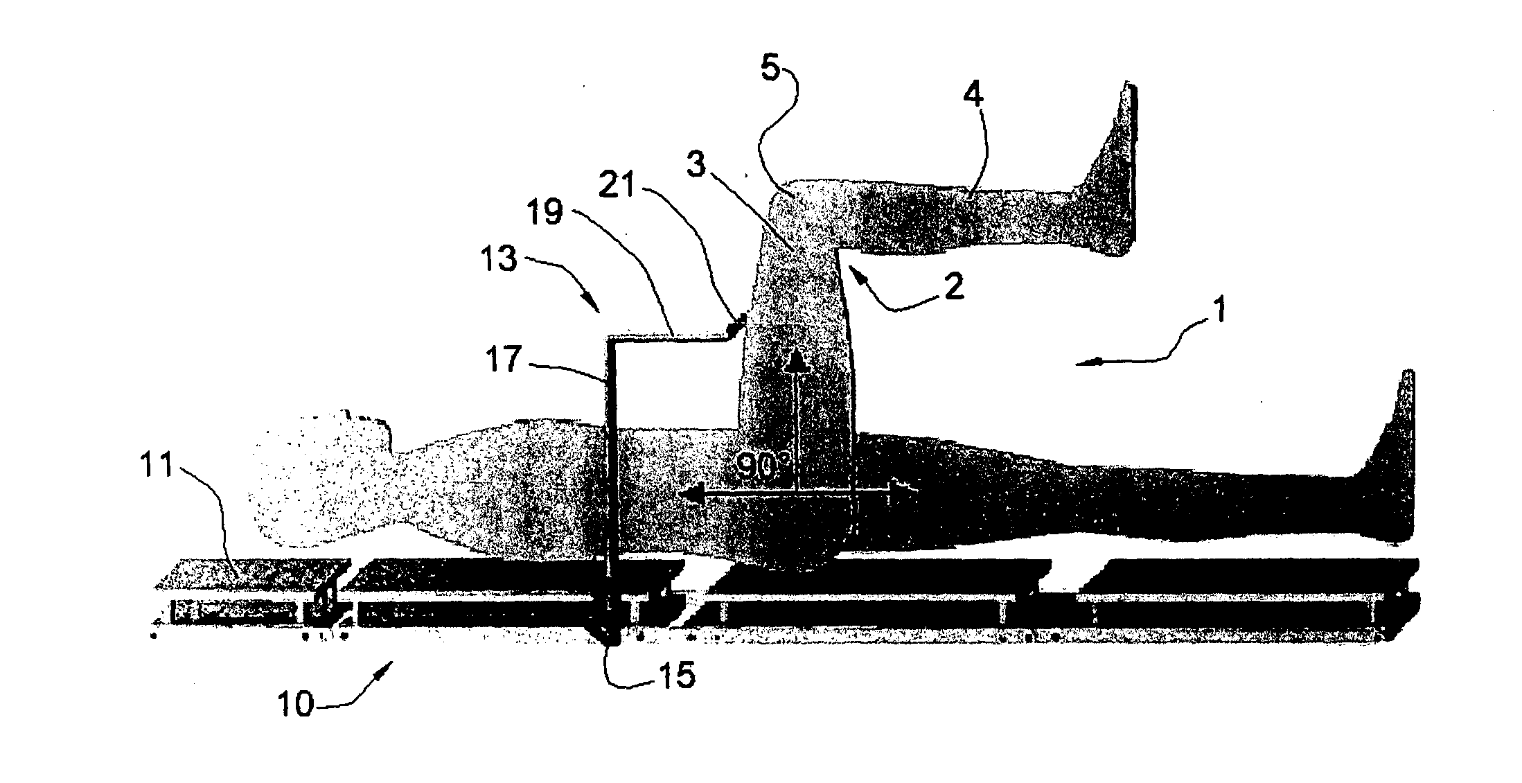
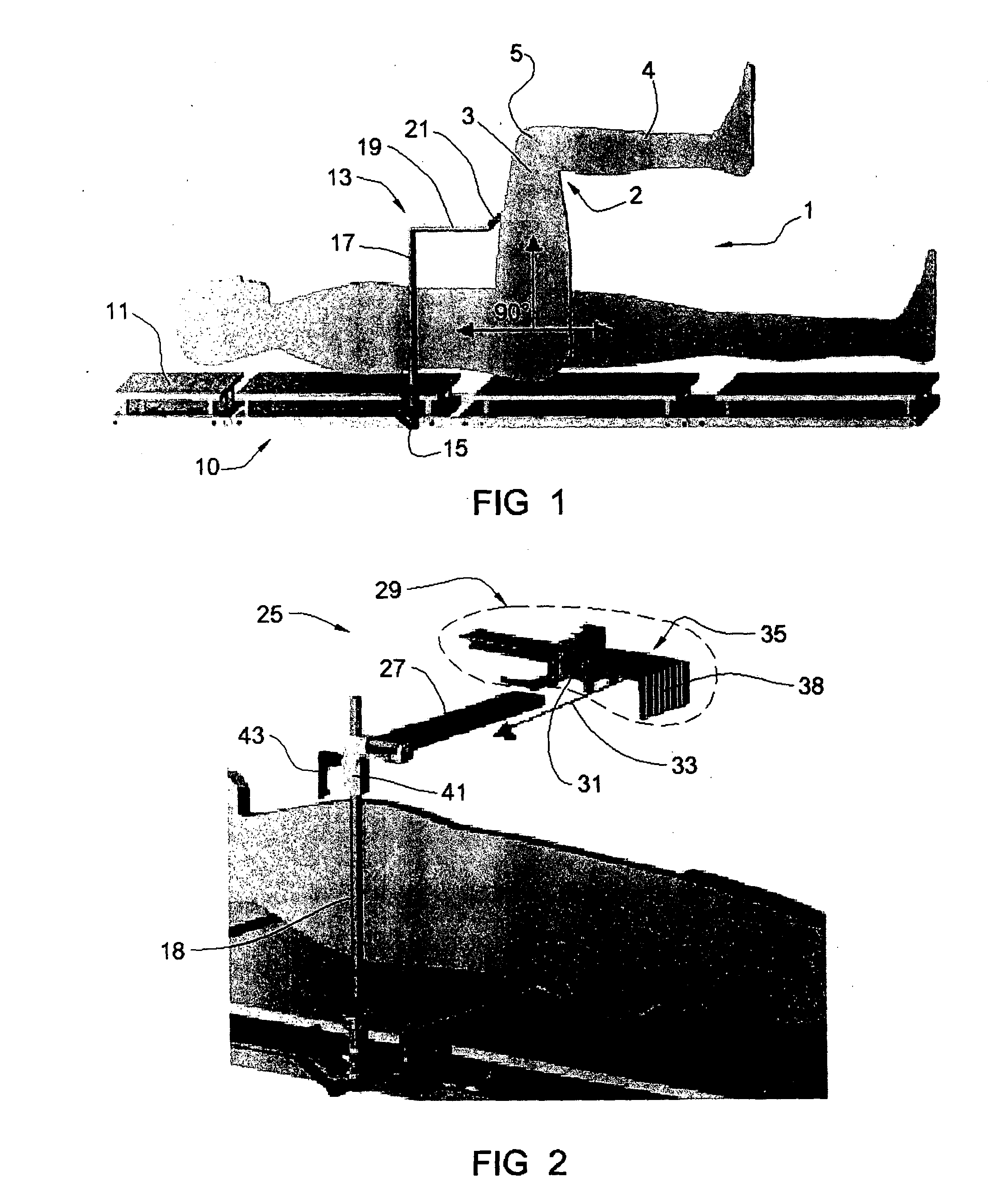
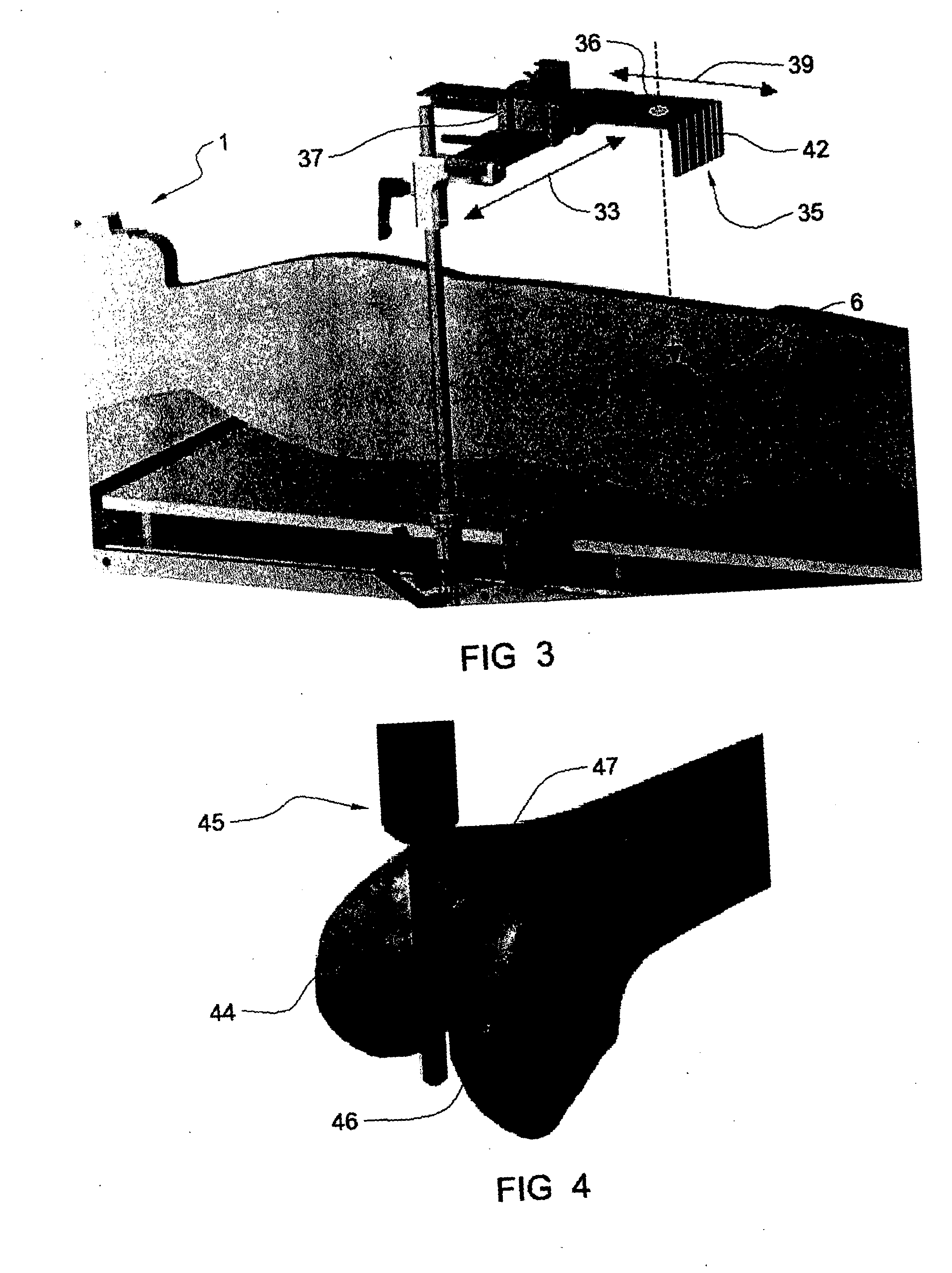
Reference is first made to FIGS. 1-3, which depict the initial positioning of a target over the hip of the patient. The patient is designated by the reference numeral 1 and has a leg 2 including an upper leg 3, a lower leg 4, and a knee 5, as well as a hip 6 (FIG. 3). A surgical table 10 has a surface 11 on which the patient 1 is positioned. A non-sterile target positioner 13 includes a non-sterile clamp 15 that is suitably clamped to the table 10, a vertical portion 17, and a horizontal portion 19 from which extends a perpendicular portion 21 designed to engage the patient's thigh when the upper leg 3 is flexed 90 degrees with respect to the patient's body (FIG. 1) and the surgical table, to position the patient on the operating table. Once the patient is properly positioned, the target positioner is removed from the clamp 15, whereupon the laser target system 25 is mounted on the clamp 15 (FIGS. 2-3).

As particularly seen in FIGS. 2 and 3, the laser target system 25 includes a b...


PUM


Abstract

An Extramedullary system of alignment for total knee arthroplasties uses a small diode laser at the center of the knee adjustable to the longitudinal axis of the femur to triangulate the center of the femoral head. It utilizes a V-Frame positioning device that fits into the distal femoral intercondylar notch and is tangent to the articular surfaces of the notch. It is also parallel to the anterior femoral cortex by using a removal tongue flange that sits flat on the filed surface of the anterior cortex. This prepositions the Distal Femoral Resector Guide within a few degrees of the center of the femoral head. An adjustment knob on the V-Frame pivots the distal femoral resector guide to the exact center of the femoral head for that particular patient accomplishing fine adjustment of the longitudinal axis of the femur. There is only one position where the laser beam will go through the center of the target no matter where you position the leg and that is when the target's bulls-eye is exactly over the rotational center of the femoral head. Since the laser confirms this position, the surgeon is assured that the alignment is accurate. The Distal Femoral Resector Guide is then fixed to bone with fixation pins and the resection made with a power saw. The laser is moved to the target mount to act as a longitudinal “laser ruler” for the remainder of the operation.

Description

BACKGROUND OF THE INVENTION The present invention relates to laser triangulation of the femoral head for total knee arthroplasty alignment instruments and surgical method. Orthopedic surgeons have been struggling with the alignment of total knee arthroplasties since their inception in the early 1970s. Basically, what is necessary is a 5-7 degree angular resection of the distal femoral condyles as related to the mechanical axis of the femur and a perpendicular resection of the proximal tibia as related to its central axis. The mechanical axis is defined as a line extending from the center of the femoral head through the center of the knee to the center of the ankle. Early on, resections of the distal femur and proximal tibia were made by visually trying to match the existing anatomy by eye. Alignment varied considerably depending on the skill of the operating surgeon. In the early 1980s, precision jigs were introduced that aligned the resections to the mechanical axis of the respec...

Claims


Application Information

Patent Timeline
Patent Type & Authority Applications(United States)
IPC IPC(8): A61B5/103A61B5/107A61B17/15
CPCA61B5/103A61B17/155A61B5/4528A61B5/107
Inventor PETERSEN, THOMAS D.
Owner PETERSEN THOMAS D
Why Eureka
Try Eureka