Device for detecting magnetic azimuth
a magnetic azimuth and sensor technology, applied in the field of earths magnetism detection devices, can solve the problems of inconvenient mounting of devices in portable information equipment, increased rapidity, and difficulty in miniaturizing devices, and achieves low power consumption, high detecting accuracy, and small size
- Summary
- Abstract
- Description
- Claims
- Application Information
AI Technical Summary
Benefits of technology
Problems solved by technology
Method used
Image
Examples
first embodiment
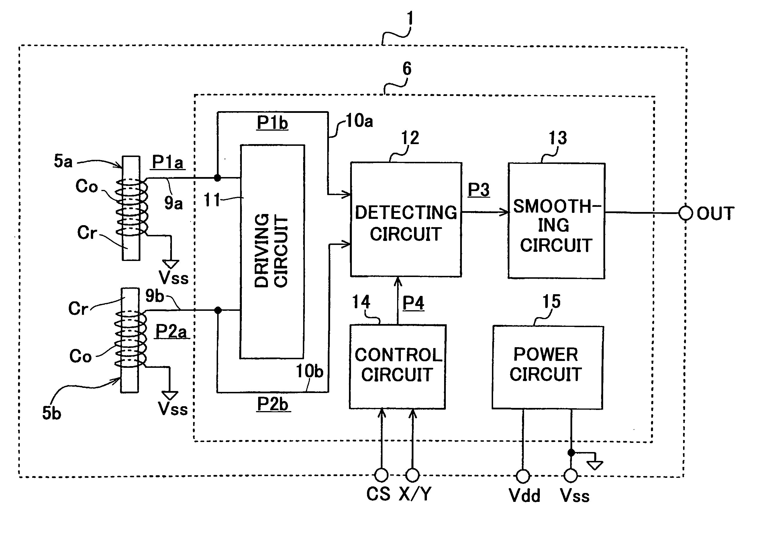
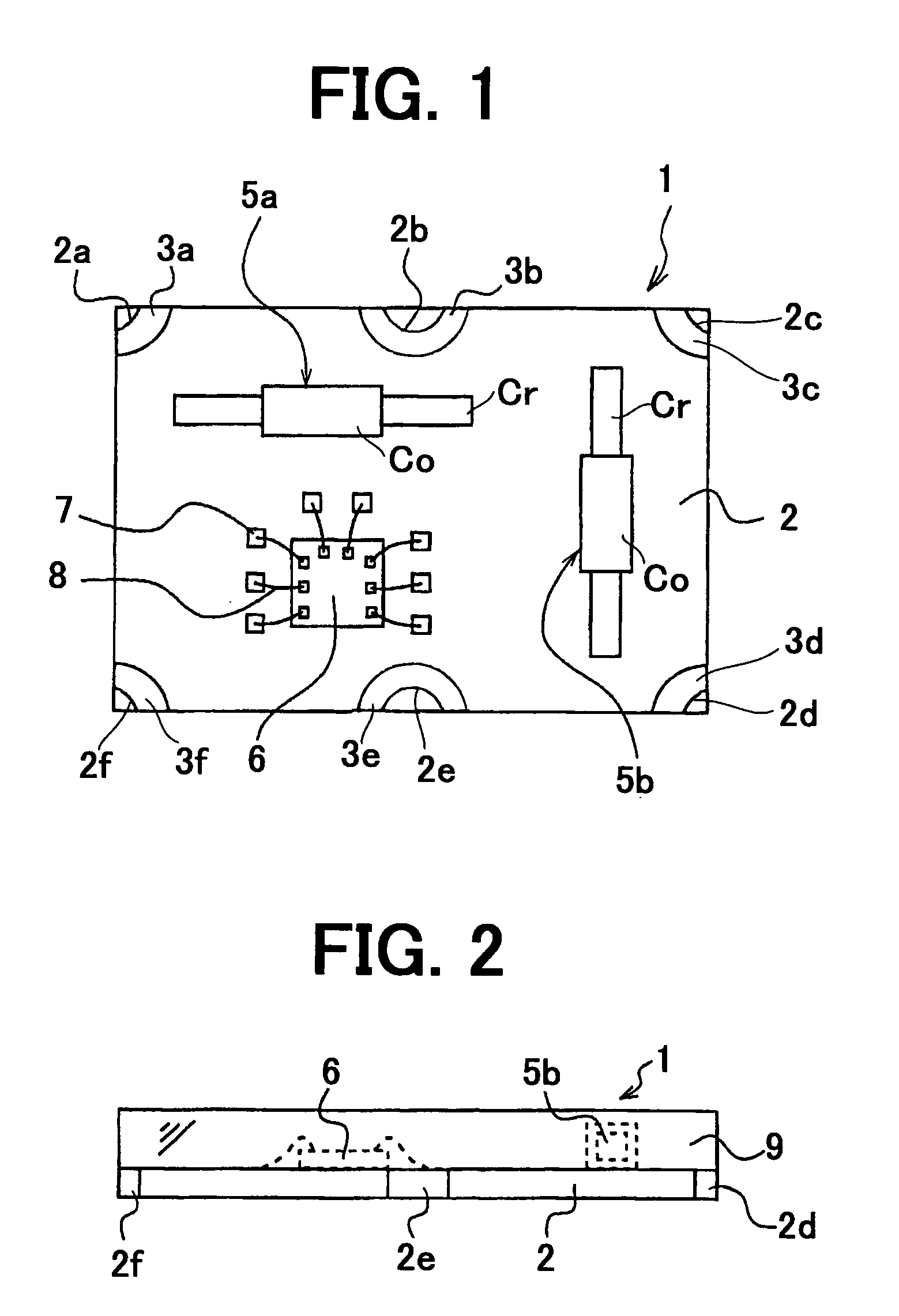
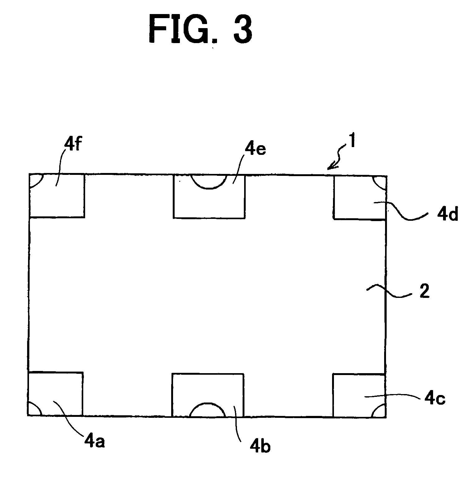
[0037]FIG. 1 is a plan view showing a magnetic azimuth detecting device according to the present invention, FIG. 2 is a side view of the device, FIG. 3 is an underside view, FIG. 4 is a block diagram showing a detecting circuit, FIG. 5 is a plan view of the device for explaining a detecting operation, and FIG. 6 is a diagram showing output characteristics.
[0038] Referring to FIGS. 1 to 3, a magnetic azimuth detecting device 1 of the present invention has a quadrilateral circuit substrate 2. The substrate 2 is preferable to be made of heat-resistant glass epoxy resin or ceramics and has a thickness of about 0.3 mm. On the four corners and opposite side walls of the substrate, through-holes 2a to 2f are formed. On the upper surface and lower surface of the substrate, upper electrodes 3a to 3f and lower electrodes 4a to 4f are mounted, surrounding the through-holes. Opposite upper electrode and lower electrode are electrically connected by a metal plate secured to the inside wall of ea...
second embodiment
[0061]FIG. 7 is a plan view showing a magnetic azimuth detecting device according to the present invention, FIG. 8 is a side view of the device, FIG. 9 is side view showing an actual device, FIG. 10 is a block diagram showing a detecting circuit, and FIG. 11 is a flowchart showing the operation of the detecting device.
[0062] The magnetic azimuth detecting device according to the second embodiment of the present invention will be explained with reference to the drawings. In the drawings, the same parts as the first embodiment are designated by the same reference numerals as the fist embodiment and a part of the explanation will be omitted.
[0063] Referring to FIGS. 7 to 9, a magnetic azimuth detecting device 20 of the present invention has the circuit substrate 2.
[0064] The magnetic sensor 5a is mounted on the substrate 2, disposed in the X-direction and secured to the substrate with solder. The magnetic sensor 5b is mounted on the substrate 2, disposed in the Y-direction and secure...
third embodiment
[0078] The method for manufacturing the magnetic azimuth detecting device as the present invention will be described with reference to FIGS. 12 through 14.
[0079] There is provided a thin substrate aggregation 30 made of BT resin (bismaleimide triazime resin). The substrate aggregation 30 comprises a plurality of substrate divisions partitioned by dicing lines 32 and 33 as shown in FIG. 13. A plurality of through-holes 31 are provided in the substrate aggregation 30 at intersections of dicing lines 32 and 33 and on the X-direction line 32. Wiring patterns (not shown) are formed on the surface of the substrate aggregation 30 by etching. Electronic parts such as magnetic sensors 5a and 5b and detecting IC are secured on the substrate aggregation 30 by surface mounting at each of the divisions.
[0080] Next, dicing process is carried out on the substrate aggregation 30. Namely, the substrate aggregation 30 is cut off along the X-direction dicing lines 32 and along the Y-direction dicing ...
PUM
 Abstract
Description
Claims
Application Information
 - R&D
- Intellectual Property
- Life Sciences
- Materials
- Tech Scout
- Unparalleled Data Quality
- Higher Quality Content
- 60% Fewer Hallucinations
Browse by: Latest US Patents, China's latest patents, Technical Efficacy Thesaurus, Application Domain, Technology Topic, Popular Technical Reports.
© 2025 PatSnap. All rights reserved.Legal|Privacy policy|Modern Slavery Act Transparency Statement|Sitemap|About US| Contact US: help@patsnap.com


