
Screw for extruder, screw extruder, and kneading extruder using the screw extruder

Inactive Publication Date: 2005-04-07
NGK INSULATORS LTD
View PDF36 Cites 12 Cited by
  • Summary
  • Abstract
  • Description
  • Claims
  • Application Information

AI Technical Summary

Benefits of technology

[0011] The present invention has been made in view of the problems of conventional techniques, and it is an object of the present invention to provide a screw for an extruder, a screw extruder, and a kneading extruder capable of effectively preventing problems that characteristics of the compressed material obtained are not unified in each part, resulting in uneven distribution, and discontinuous portions (screw marks) are formed inside the obtained compressed product.

Problems solved by technology

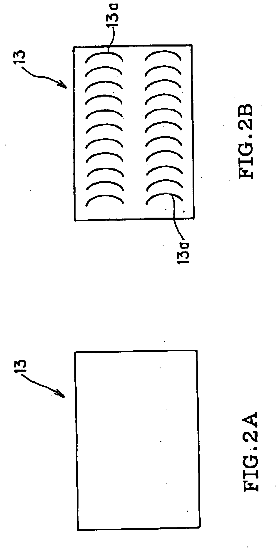
However, in the screw extruder as described above, there have been problems that characteristics (a density, an ingredient composition, a powder gain size, and moisture content, for example) of the obtained compressed product are disproportionated in each part resulting in uneven distribution, and as shown in FIG. 2B, a number of discontinuous portions (screw marks 13a) are formed inside the obtained compressed product 13.
When the ceramic green body obtained by the screw extruder mentioned above are used for the extrusion forming material for producing the porous honeycomb filter, the above-mentioned problems become especially obvious.
Specifically, when the ceramic green body with not uniform density and uneven density distribution are used for the extrusion forming material, the porosity of the porous honeycomb filter, which is a final product, becomes heterogeneous, resulting in uneven distribution.
That is, there has been a defect in that performances (mechanical strength and filter functions, etc.) of the porous honeycomb filter are adversely affected.
When the ceramic green body with a number of discontinuous portions (screw marks) formed inside is used for the extrusion forming material, since the screw mark portion is fragile (because of the density lower than that of other portions), inferior quality is caused, such as “tears” and large “pores” of the solid body or the porous honeycomb filter, which is a final product.
Hence, there are problems that the porous honeycomb filter is liable to be damaged as well as a desired filter performance is difficult to be functioned.

Method used


Image

  • Screw for extruder, screw extruder, and kneading extruder using the screw extruder
  • Screw for extruder, screw extruder, and kneading extruder using the screw extruder
  • Screw for extruder, screw extruder, and kneading extruder using the screw extruder

Examples


example

[0065] The present invention will be described more specifically with examples below; however, the present invention is no longer limited to these examples. The average particle diameter of an aggregate particle material used in the examples and the comparative examples below used the 50% particle diameter value measured by an X-ray translucent grain-size distribution measurement device (Sedigraph type 5000-02 from Shimadzu Corporation, for example) using a liquid-phase sedimentation method as a measuring principle.

(COMPARATIVE EXAMPLE 1, EXAMPLE 1)

[0066] As an aggregate particle material, a cordierited material was prepared by mixing talc (an average particle diameter of 20 μm) 41.6 mass percent, kaolin(an average particle diameter of 10 μm) 10.1 mass percent, aluminum hydroxide (an average particle diameter of 1 μm) 24.5 mass percent, and silica (an average particle diameter of 20 μm) 13.7 mass percent.

[0067] To the aggregate particle material 100 mass part, methyl cellulose 5 ...

example 1

[0075] The work material mentioned above was compressed with the screw extruder 21 shown in FIG. 3. The screw extruder 21 included the screw 29 having the interrupted blades 27c and the continuous blade 27a as the stirring blade 27. The interrupted blades 27c were arranged over 20% range of the length of the drive shaft 25 from the leading edge.

[0076] The sectoral single blades 27b were arranged adjacent to the leading edge of the drive shaft 25 as the interrupted blades 27c. The shape of the single blade 27b was a sector with a central angle of 40°, and the height thereof was 40 mm from the surface of the drive shaft 25. The arranging manner of the single blade 27b was the two single blades 27b were arranged at positions of symmetry about the drive shaft 25, respectively; and the two single blades 27b were arranged so that planes including blade surfaces intersect to each other (i.e., the blade surfaces of the two single blades 27b were inclined at an angle of 16° to a plane norma...


PUM

PropertyMeasurementUnit
Fractionaaaaaaaaaa
Lengthaaaaaaaaaa
Pressureaaaaaaaaaa

Abstract

A screw for an extruder includes a drive shaft and stirring blades arranged on the drive shaft, and blades among the stirring blades arranged at least part of the drive shaft adjacent to the leading edge of the drive shaft are interrupted blades, each of continuous surfaces of the interrupted blades being less than a full circle about the drive shaft. The screw is capable of effectively preventing problems that characteristics of a compressed material obtained are not unified in each part, resulting in uneven distribution, and discontinuous portions (screw marks) are formed inside the obtained compressed product.

Description

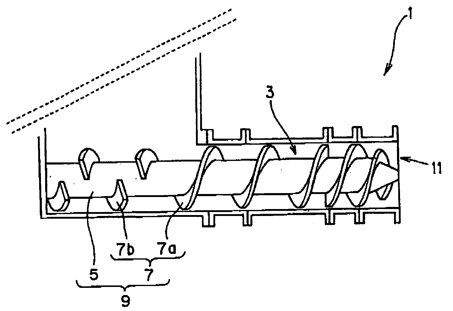
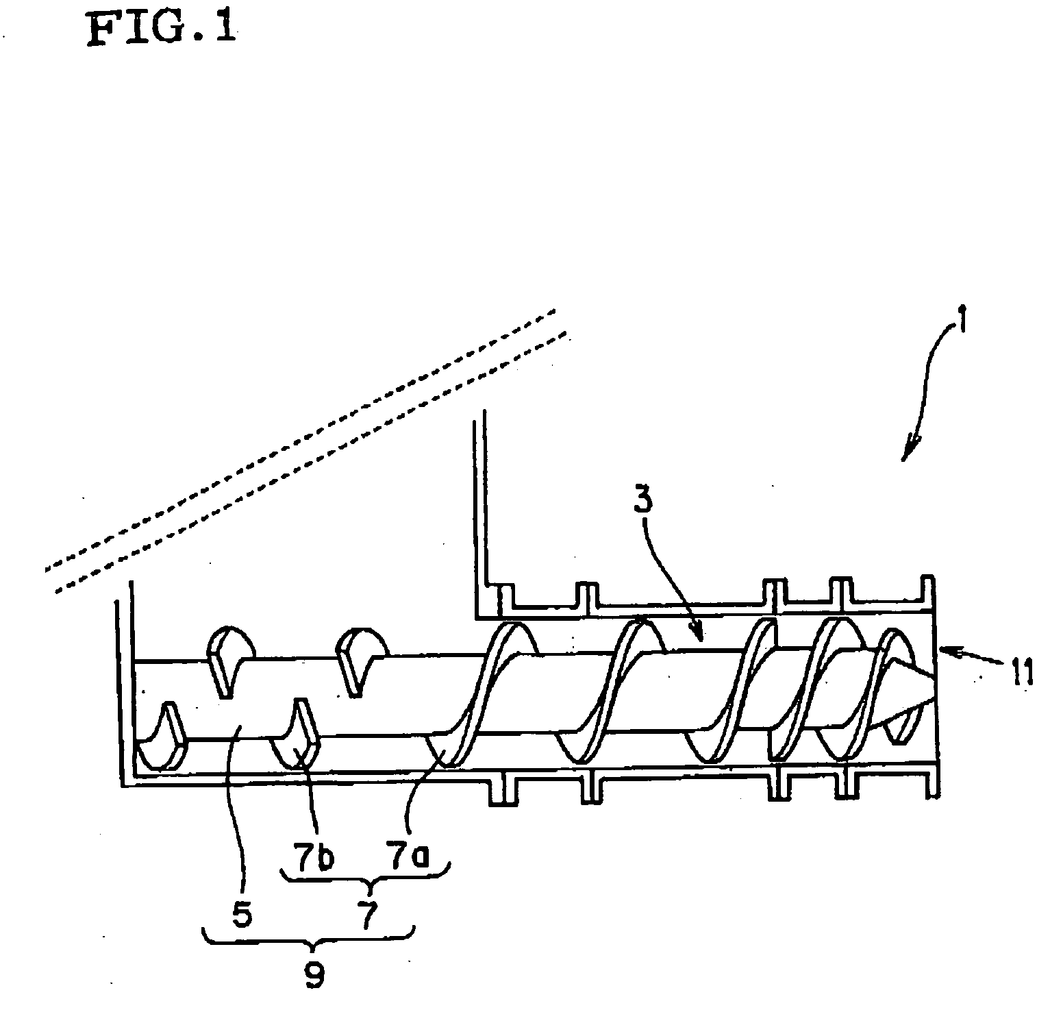
BACKGROUND OF THE INVENTION [0001] 1. Field of the Invention [0002] The present invention relates to a screw extruder and a kneading extruder suitably used for manufacturing a ceramic green body, and in particular relates to a structure of a screw for an extruder. [0003] 2. Description of the Related Art [0004] For example, as shown in FIG. 1, a screw extruder 1 has been proposed in that a screw 9 including a drive shaft 5 and stirring blades 7 arranged on the drive shaft 5 is arranged inside a hollow cylindrical barrel 3. (see Japanese Unexamined Patent Application Publication No. 9-94818 and No. 10-100131, for example). [0005] A screw extruder 1 shown in FIG. 1 Includes a crew 9 having a spiral stirring blade 7a, which is continuously arranged on the surface of a drive shaft 5 so as to wind therearound as a stirring blade 7, and a plurality of sectoral stirring blades 7b. The screw extruder 1 may also be called as a kneader (auger machine) and has insufficient kneading functions. ...

Claims


Application Information

Patent Timeline
IPC IPC(8): B01F7/08B28B13/02B29C48/03B29C48/50B29C48/76B30B11/24
CPCB29C47/0009B29C47/585B30B11/246B29C47/6075B29C47/76B29C47/60B29C48/03B29C48/501B29C48/76
Inventor HAYASHI, SHINZO
Owner NGK INSULATORS LTD
Learn More