Separation column

a technology of separation column and chromatographic column, which is applied in the direction of separation process, filtration separation, instruments, etc., can solve the problems of corroding the metal column, affecting the quality of the chromatographic column, and requiring more work, so as to reduce the pressure difference, shorten the analysis time, and facilitate various operations

Inactive Publication Date: 2005-04-14
GL SCI
View PDF12 Cites 5 Cited by
  • Summary
  • Abstract
  • Description
  • Claims
  • Application Information

AI Technical Summary

Benefits of technology

[0013] In the present invention, there is provided a separation column which is formed as a double-wall tube, comprising: an inner pipe; an outer pipe; and a union nut, the union nut being freely screwed to an end of the outer pipe; the outer pipe being divided so as to be freely inserted and extracted. As a result of this, when the separation column is formed by screwing in the union nut, the fixing of the position of the inner tube is performed by the union nut and, therefore, the torque of the union nut is transmitted to the inner tube and there is a possibility that the inner tube is twisted or strains are given to the inner tube. At this time, however, by shifting the fitting of the outer tube to make an adjustment, the torque of the union nut can be prevented from being transmitted to the inner tube. Or alternatively, the torque of the union nut can be corrected.
[0014] As a result of this, it is possible to completely ensure the performance of the separation tube without causing any damage to the performance of the separation column and the analysis capacity can be ensured. Furthermore, there is no space for a dead volume and it is possible to positively prevent a dead volume. Needless to say, the precision working of the inner tube is possible owing to the inner and outer double-wall structure. Besides, the construction of the outer tube is simple and the number of parts is small for the whole separation column. Hence, the separation tube provides convenience in use and is easy to use and advantageous in terms of cost.
[0016] Furthermore, in the present invention, in the above-described separation column, the outer tube has one or more holes or connection parts which communicate with a space between the inner tube and the outer tube. As a result of this, it becomes possible to reduce a pressure difference between the outer tube and the inner tube by putting a fluid between the outer tube and the inner tube in order to resist the liquid pressure in the inner tube, it becomes possible to cause a target component concentrated at the inlet of the column to be eluted by raising the temperature, and by bringing the inner tube into contact with the outside air or another fluid etc., it becomes possible to easily perform various operations such as temperature regulation and pressure regulation. This is effective in protecting the inner tube and shortening the analysis time.
[0017] Furthermore, in the present invention, in the above-described separation tube, at least part of the union nut is formed by a transparent material. As a result of this, this formed transparent part enables the fixing of the inner tube in position to be visually recognized and the tightening condition when the ferrule is used can be checked. Thus, operations can be perfectly carried out.

Problems solved by technology

However, a chromatographic column made of metal is corroded by a mobile phase used in the separation of a moving organism sample etc.
Besides, in the manufacturing process of a chromatographic column made of metal, the smaller the inside diameter of the column, the more conspicuous the roughness of the surface of a wall face will tend to be.
Therefore, the smaller the column diameter, the higher the production cost and the more expensive the column.
On the other hand, in the case of a glass column, which is frequently used, cracks are produced from worked parts such as screws and flanges.
Furthermore, a glass column has the drawbacks of low pressure stability, low resistance to high pressure and susceptibility to failure.
Therefore, the number of parts is large and a simple connection is not obtained.
Therefore, it is necessary that the plunger etc. enter the end of the glass tube, which is the inner tube, and hence it is difficult to make an inner tube having a small diameter.
Furthermore, when only the pipe end is formed wide, this provides the drawbacks of a difficulty in manufacturing, inconvenience of use, susceptibility to cracking, etc.
Also, when Teflon (registered trade name), which has no pressure resistance, etc. are used in the inner tube, this provided the fear of a fracture due to liquid pressure.
Furthermore, in chromatography, the lower the temperature, the lower the moving speed of sample components within the column, with the result that elution can be delayed.
Therefore, there has been no effective means although it is possible to cause a target component to be eluted by raising the temperature after the target component is concentrated at the inlet of the column.

Method used


Image

  • Separation column
  • Separation column
  • Separation column

Examples


example 1

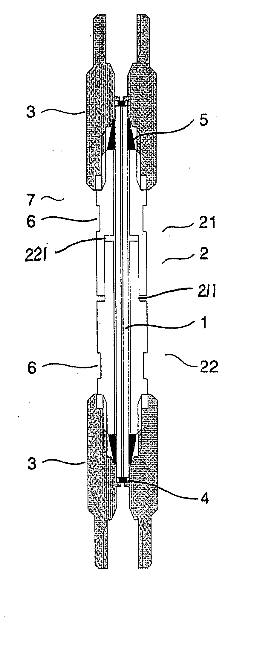
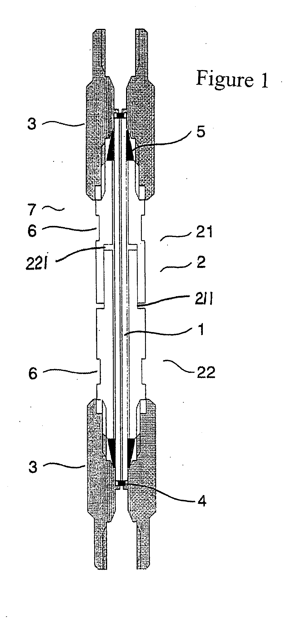
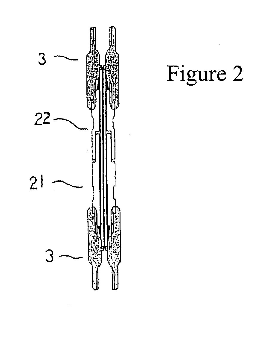
[0040] A microcapillary column 1 as an inner tube which is selected according to the purpose is inserted into an outer tube 2. At this time, both ends of the microcapillary column 1 have portions exposed from the outer tube 2. Ferrules 5, 5 are fitted into both ends beforehand. Next, union nuts 3, 3 are put on both ends of the outer tube 2 and screwed in. At this time, both ends of the microcapillary column 1 are inserted into a through hole 31 of the union nuts 3, 3 and the leading end of the microcapillary column 1 is brought into contact with a filter 4. As the union nuts 3, 3 are crewed in, the ferrule 5 is caused to abut against a taper 311 formed in the through hole 31 and tightens this taper, thereby forming a separation column 7. (FIG. 1, FIG. 6)

[0041]FIG. 9 shows a chromatogram obtained by conducting an experiment using Embodiment 1 under the following conditions.

[0042] A microcapillary column having an inside diameter of 0.3 mm, in particular, lacks physical endurance an...

example 2

[0051] Example of application to an analysis of benzpyrene in the environmental water

[0052] A column the outer tube 2 of which has three hole portions 26, 26, 26 is used. A drain pipe 28 is connected to one of the hole portions 26 and is locked by a pinch cock. The remaining two hole portions 26, 26 are connected to a circulating constant-temperature water tank 29 by use of connection parts 28, 28 and methanol at 4° C. is circulated. The temperature of the whole column is regulated by use of a column oven at 7° C. The temperature in the interior of the column reaches temperature equilibrium, though this depends on the flow rate of the circulating constant-temperature water tank and the inner tube diameter, and the temperature of the inner tube is controlled to 4° C. When a sample is introduced at 4° C., the matrix components other than the target benzpyrene are eluted first. In 2 minutes after the approach of the matrix components to the outlet, the circulation in the circulating c...

example 3

[0071] It is not always necessary that a separation column of the present invention is a straight tube, and the invention can also be applied to bent tubes such as a U-shaped tube.

[0072] This separation column can be used in a case where the separation column is connected directly to an injector loop of liquid chromatography and a solid phase is extracted and in pretreatment for the trapping of the air. In an integrated protective tube, it is impossible to ensure the accuracy of a connection part of a union nut 3 and the fabrication is difficult. In this system of the invention, bent tube portions and straight tube portions can be fabricated as separate parts and, therefore, the accuracy of the connection parts can be increased.

[0073] When a straight tube is to be attached to a loop portion of an injector, piping for connection is required; hence parts such as joints and piping are necessary and labor is also required. Furthermore, because the interior of the piping is not filled ...


PUM

PropertyMeasurementUnit
pressureaaaaaaaaaa
diameteraaaaaaaaaa
diameteraaaaaaaaaa

Abstract

In the field of substance separation which uses the flow of a fluid, it is necessary to reduce the inside diameter of a separation column in order to meet the tendency to reduce the volume of an organic solvent used. The smaller the volume of a target sample which is caused to flow, the higher the concentration of the target sample, thereby permitting a high-sensitivity analysis. For this purpose, it is necessary to reduce the diameter of a separation column. Therefore, the manufacturing of such a separation column is difficult and besides the separation column becomes apt to fracture. Therefore, the separation column is fabricated as a double-wall tube constituted by an outer tube and an inner tube in such a manner that the outer tube is separated so as to be freely inserted and extracted. Furthermore, a union is fitted to the end of the outer tube by use of a screw thereby to prevent torsions between the outer tube and the inner tube and strains and, at the same time, to eliminate a space for a dead volume.

Description

BACKGROUND OF THE INVENTION [0001] 1. Field of the Invention [0002] The present invention relates to a separation column and, more particularly, to an analytical column and a separation column used in liquid phase extraction and pretreatment. [0003] 2. Description of the Related Art [0004] In a chromatographic column for separating substances by using a fluid, the volume of the fluid which fills the interior of the column will decrease with decreasing inside diameter of the column in proportion to the square of the inside diameter. A fluid used in a chromatographic column contains mainly an organic solvent. Therefore, it is necessary to make efforts to reduce the volume of the fluid from the problem of the global environment and the like, and there is a tendency to minimize the volume of the fluid. For this purpose, reducing the inside diameter is the most effective means. [0005] On the other hand, in the analysis field where chromatographic columns are mainly used, the material for...

Claims


Application Information

Patent Timeline
Patent Type & Authority Applications(United States)
IPC IPC(8): G01N30/60
CPCG01N30/60G01N30/6047G01N30/6004
Inventor NYUDO, MASAHIKOTAHARA, MINEO
Owner GL SCI
Why Eureka
Try Eureka