De-blocking filter processing apparatus and de-blocking filter processing method

a filter processing and filter technology, applied in the field of deblocking filter processing apparatus and deblocking filter processing method, can solve the problems of blocky artifacts, blocky artifacts in images obtained by decoding pictures, and inability to meet the needs of the above filter design, and achieve the effect of high picture quality

Inactive Publication Date: 2005-04-14
PANASONIC CORP
View PDF2 Cites 87 Cited by
  • Summary
  • Abstract
  • Description
  • Claims
  • Application Information

AI Technical Summary

Benefits of technology

It is an object of the present invention to provide a de-blocking filter processing apparatus and de-blocking filter proc

Problems solved by technology

Blocky artifacts often occur in images obtained by decoding pictures subjected to low bit-rate video compression due to quantization noise as well as motion compensation.
However, for the interframe wavelet video coding scheme, which has gained a lot of interest lately and may possibly become the future general video coding standard, the above filter design may not be the most appropriate.
Hence, block-based motion estimation/compensation is the main stage causing blocky artifacts in this scheme.
Blocky artifacts are caused, in particular, by inaccurate motion prediction and quantization when motion estimation/compensation is carried out at a

Method used


Image

  • De-blocking filter processing apparatus and de-blocking filter processing method
  • De-blocking filter processing apparatus and de-blocking filter processing method
  • De-blocking filter processing apparatus and de-blocking filter processing method

Examples


embodiment 1

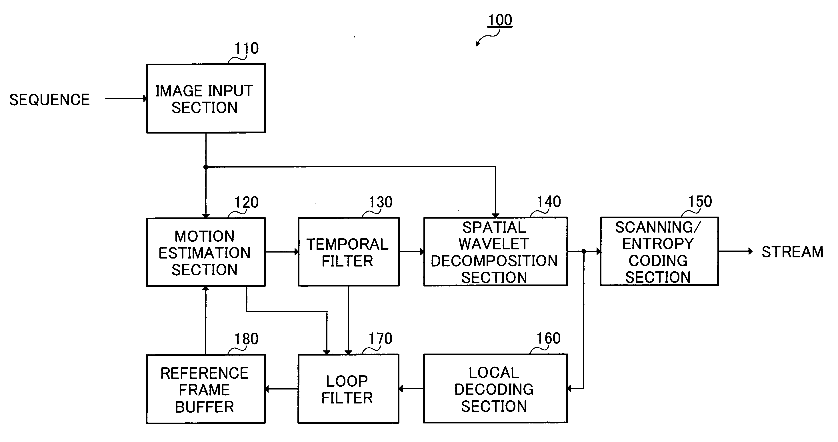
FIG. 4 is a block diagram showing the configuration of a video coding apparatus that has a loop filter according to Embodiment 1 of the present invention.

Video coding apparatus 100 shown in FIG. 4 has an image input section 110, motion estimation section 120, temporal filter 130, spatial wavelet decomposition section 140, scanning / entropy coding section 150, local decoding section 160, loop filter 170, and reference frame buffer 180.

Image input section 110 groups a predetermined number (fixed number or variable number) of neighboring frames in an input video sequence as one GOP, and then outputs the frames to motion estimation section 120. Image input section 110 may also output a frame directly to spatial wavelet decomposition section 140 in order to obtain a coded frame independently of other frames for the purpose of random access or error recovery, for example.

Motion estimation section 120 references a reference frame temporarily stored in reference frame buffer 180, and p...

embodiment 2

FIG. 10 is a block diagram showing the configuration of a video decoding apparatus that has a loop filter according to Embodiment 2 of the present invention.

In this embodiment, a general case is described in which a filter that executes de-blocking filter processing according to the present invention is used on both the encoder side and the decoder side. The encoder-side filter is similar to loop filter 170 described in Embodiment 1, and therefore a description thereof is omitted here.

Video decoding apparatus 200 shown in FIG. 10 has an inverse scanning / inverse entropy coding section 210 that performs inverse scanning and inverse entropy coding on a stream input from a corresponding video coding apparatus, a spatial wavelet composition section 220 that performs spatial wavelet composition on generated frames, a temporal filter 230 that performs temporal filter processing on frames other than independent coded frames, a motion compensation section 240 that performs motion compens...

embodiment 3

FIG. 11 is a block diagram showing the configuration of a video decoding apparatus that has a post filter according to Embodiment 3 of the present invention. The video decoding apparatus of this embodiment has a similar basic configuration to that of video decoding apparatus 200 described in Embodiment 2, and therefore identical configuration elements are assigned the same reference codes and detailed descriptions thereof are omitted.

In this embodiment, a general case is described in which a filter that executes de-blocking filter processing according to the present invention is used only on the decoder side.

Video decoding apparatus 300 shown in FIG. 11 has a configuration in which a post filter 310 is provided instead of loop filter 260 in video decoding apparatus 200 shown in FIG. 10.

Post filter 310 applies a processing similar to the de-blocking filter processing described in detail in Embodiment 1 to reconstructed frames from picture addition section 250, and outputs clear...


PUM


Abstract

A de-blocking filter processing apparatus that achieves high picture quality without consuming processing apparatus power unnecessarily. A loop filter 170 used as a de-blocking filter processing apparatus first acquires a variable-size motion estimation block in a frame for which motion estimation processing is performed. Then, de-blocking filter processing is applied adaptively to a frame for which motion estimation processing is performed, in accordance with the acquired motion estimation block. Application of de-blocking filter processing is executed only at a boundary between a particular motion estimation block and a motion estimation block adjacent to that motion estimation block in a frame for which motion estimation processing is performed.

Description

BACKGROUND OF THE INVENTION 1. Field of the Invention The present invention relates to a de-blocking filter processing apparatus and de-blocking filter processing method to be used in any advanced multimedia data coding, and more particularly to any video coding using variable block size based motion prediction. 2. Description of Related Art A variety of filters are generally used in video compression technologies in order to improve picture quality and the compression ratio. Blocky artifacts often occur in images obtained by decoding pictures subjected to low bit-rate video compression due to quantization noise as well as motion compensation. One of the main tasks of a de-blocking filter processing apparatus (hereinafter referred to as “de-blocking filter” or simply “filter”) is to smooth the boundaries of the blocks in the decoded picture so that these blocky artifacts are reduced or removed. A de-blocking filter may be a post filter that achieves high picture quality by remov...

Claims


Application Information

Patent Timeline
IPC IPC(8): H04N19/50H03M7/30H03M7/36H04N7/12H04N19/117H04N19/134H04N19/136H04N19/137H04N19/157H04N19/159H04N19/167H04N19/196H04N19/33H04N19/423H04N19/51H04N19/513H04N19/63H04N19/80H04N19/82H04N19/86H04N19/91
CPCH04N19/159H04N19/176H04N19/63H04N19/527H04N19/117H04N19/82H04N19/61
Inventor SHEN, SHENG MEILEE, MEN HUANGHONDA, YOSHIMASA
Owner PANASONIC CORP
Why Eureka
Try Eureka