Digital phase-locked loop circuit

Inactive Publication Date: 2005-04-14
TEXAS INSTR INC
View PDF4 Cites 31 Cited by
  • Summary
  • Abstract
  • Description
  • Claims
  • Application Information

AI Technical Summary

Benefits of technology

[0014] The constitution of the second phase comparator and frequency division ratio control part in said second digital phase-locked loop circuit may be the same as t

Problems solved by technology

However, the conventional DPLL circuit has the following problem.
That is, when the reference clock varies and its phase difference from the feedback clock increases, the period of the output clock becomes immediately disturbed, increasing jitter.
Although this phenomenon is momentary, it is still undesirable for the DPLL circuit applications, especially in the fields of audio and image processing, because an increase in jitter of the DPLL output aff

Method used


Image

  • Digital phase-locked loop circuit
  • Digital phase-locked loop circuit
  • Digital phase-locked loop circuit

Examples


embodiment 1

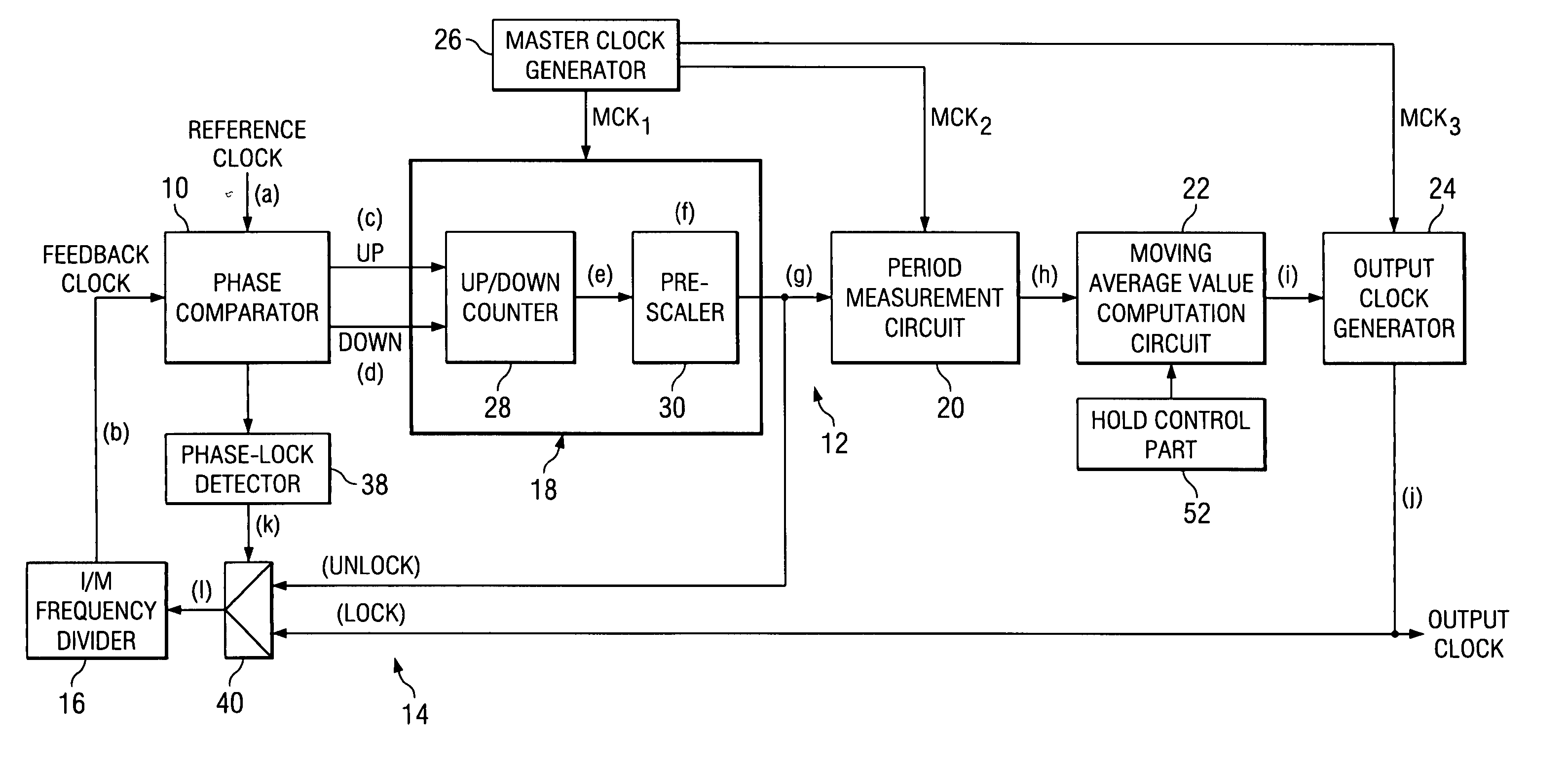
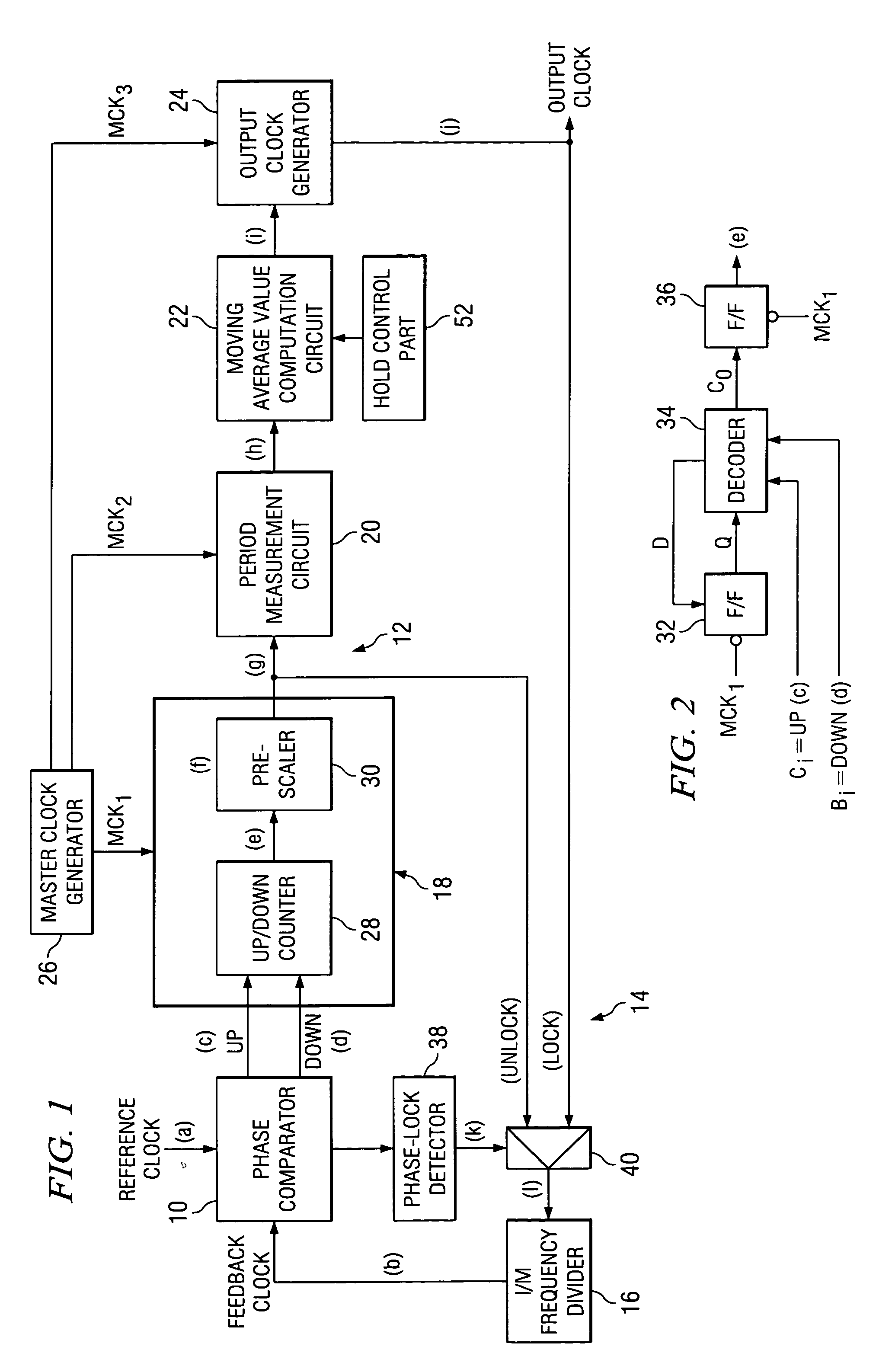
[0029]FIG. 1 is a diagram illustrating the constitution of the digital phase-locked loop (DPLL) circuit in Embodiment 1 of the present invention. The DPLL circuit of this embodiment is a multiplier DPLL circuit that generates locked output clock j at a frequency M-times (where M is an integer of 2 or larger) that of input reference clock a. Generally speaking, it is has a phase-locked loop composed of phase comparator 10, control oscillation part 12 and feedback part 14.

[0030] Feedback part 14 contains frequency divider 16 that generates feedback clock b at 1 / M times the frequency division for of output clock j. Phase comparator 10 compares the phase of reference clock a and feedback clock b, and outputs digital synchronization control signals c, d corresponding to the phase difference. More specifically, from the difference in time between the edge of reference clock a and the edge of feedback clock b, the lead / lag relationship or phase difference between the two clocks is detecte...

embodiment 2

[0057]FIG. 9 is a diagram illustrating the constitution of the DPLL circuit in Embodiment 2. Part numbers used in Embodiment 1 (FIG. 1) that correspond to parts with the same constitutions and functions are used here. The most significant characteristic feature of Embodiment 2 is that phase comparator 54 and range counter 56 improve lock range.

[0058] Like phase comparator 10, phase comparator 54 compares the phase of reference clock a and feedback clock b, and corresponding to the phase difference, outputs digital synchronization control signals m, n. The phase comparator has a lower phase difference detection sensitivity than phase comparator 10, and when the phase difference between the two clocks a, b exceeds a prescribed upper limit (e.g., ⅛ of a period), corresponding to the lead / lag relationship between the two clocks, it selectively outputs either up-count enable signal m or down-count enable signal n of the square wave pulse. Here, said up-count enable signal m is output wh...


PUM


Abstract

The object of the invention is to obtain a stable, locked clock with reduced output jitter in a digital phase-locked loop circuit. Control oscillating part 12 has frequency divider 18, period measurement circuit 20, moving average value computation circuit 22, and output clock generator 24. In intermediate oscillating frequency divider 18, as a result of tracking to synchronization control signals c, d from phase comparator 10, there is a wide variation in the period of intermediate clock g. However, by means of period measurement circuit 20 and moving average value computation circuit 22, varying slowly with a small fluctuation amplitude, period i of the moving average is obtained, and a stable output clock j that tracks reference clock a slowly and reliably is obtained from output clock generator 24.

Description

FIELD OF THE INVENTION [0001] The present invention pertains to a digital phase-locked loop (DPLL) circuit. More specifically, the present invention pertains to a DPLL circuit that generates a synchronizing clock at a multiple of the reference clock frequency. BACKGROUND OF THE INVENTION [0002] A DPLL circuit is a PLL circuit in which all parts of the loop are digitally constituted. Since it does not require a voltage-controlled oscillator (VCO), there is no need to worry about frequency drift, which is primarily a function of variations in the power source; thus, it is very stable and reliable, Also, the circuit layout is less restrictive, which is beneficial for IC design. A conventional multiplier type DPLL circuit is composed of a control oscillator made up of a frequency divider that frequency-divides at the prescribed frequency division ratio of the master clock, which has a frequency sufficiently higher than that of the input reference clock to generate an output clock, a fre...

Claims


Application Information

Patent Timeline
IPC IPC(8): H03K5/00G06F1/04H03L7/06H03L7/087H03L7/099H03L7/18
CPCH03L7/087H03L7/18H03L7/0992
Inventor OKITA, SHIGERU
Owner TEXAS INSTR INC
Why Eureka
Try Eureka