Apparatus and method for depositing large area coatings on planar surfaces

a technology of planar surface and uniform coating, which is applied in the direction of chemical vapor deposition coating, coating, plasma technique, etc., can solve the problems of reducing the uniformity of the coating, the cost of equipping each plasma source with an individual delivery system and the increase of flow control

Inactive Publication Date: 2005-04-14
SABIC INNOVATIVE PLASTICS IP BV
View PDF6 Cites 45 Cited by
  • Summary
  • Abstract
  • Description
  • Claims
  • Application Information

AI Technical Summary

Benefits of technology

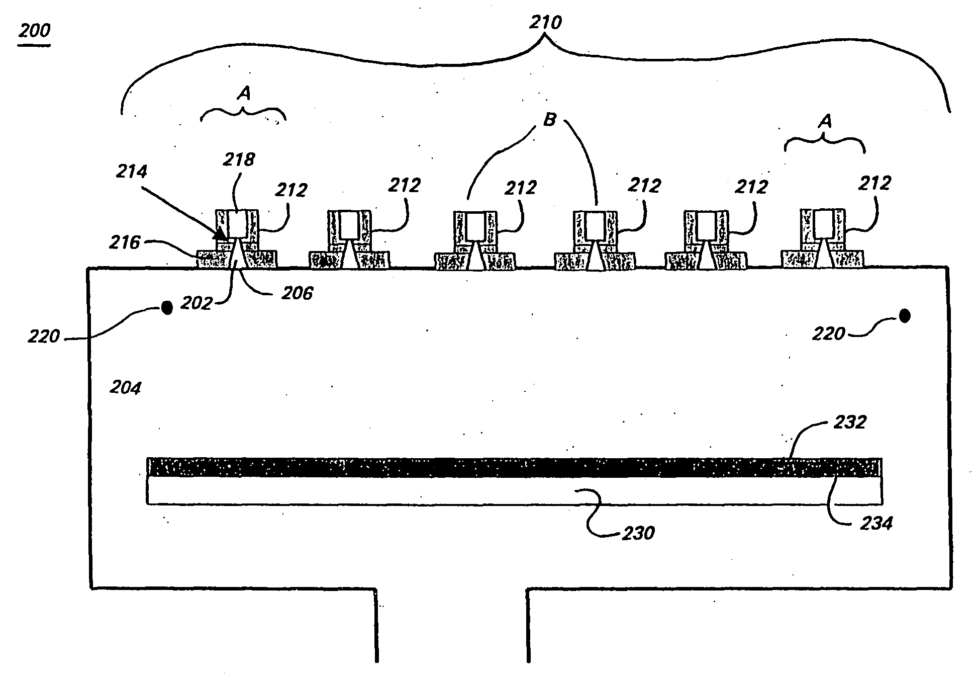
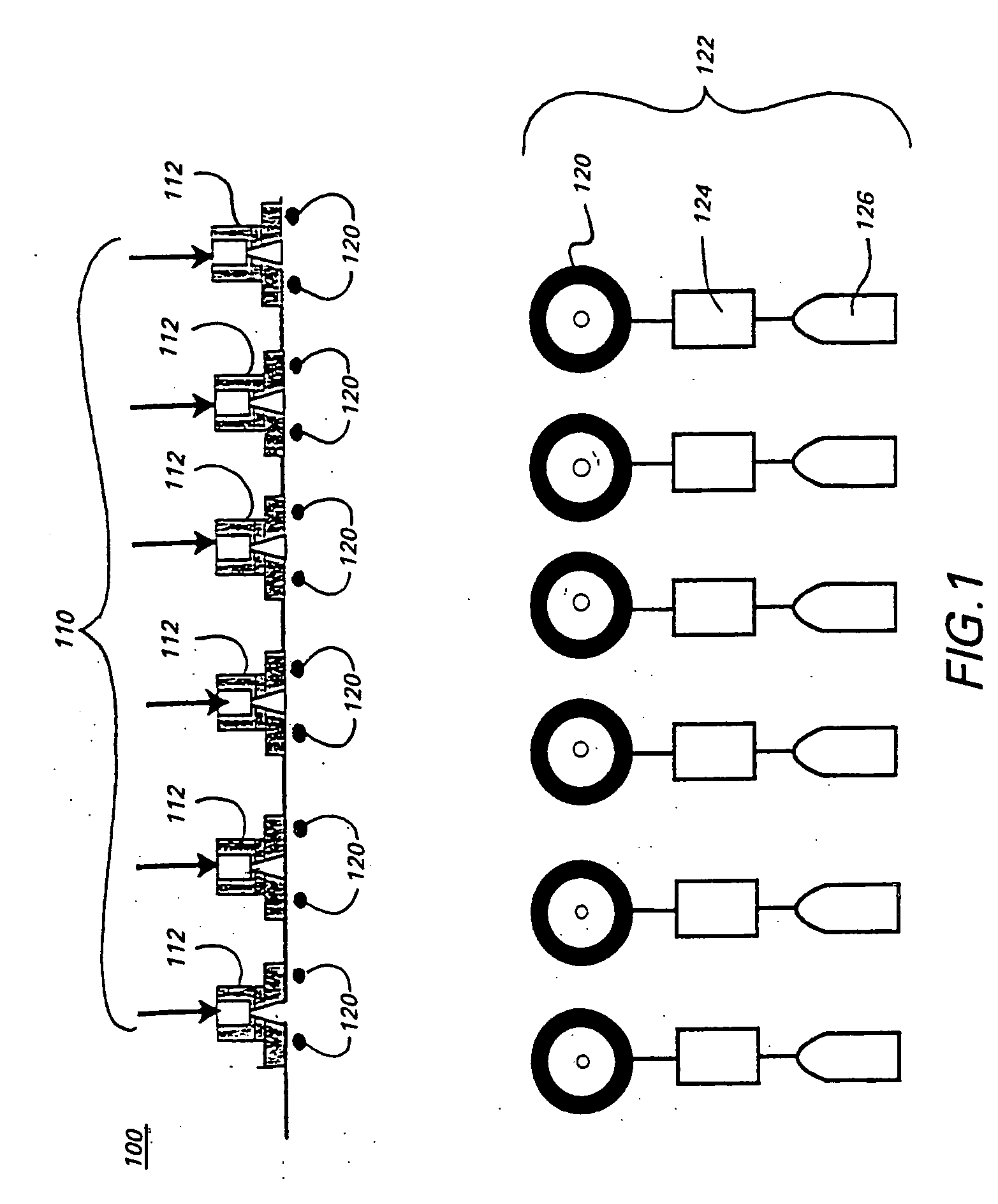
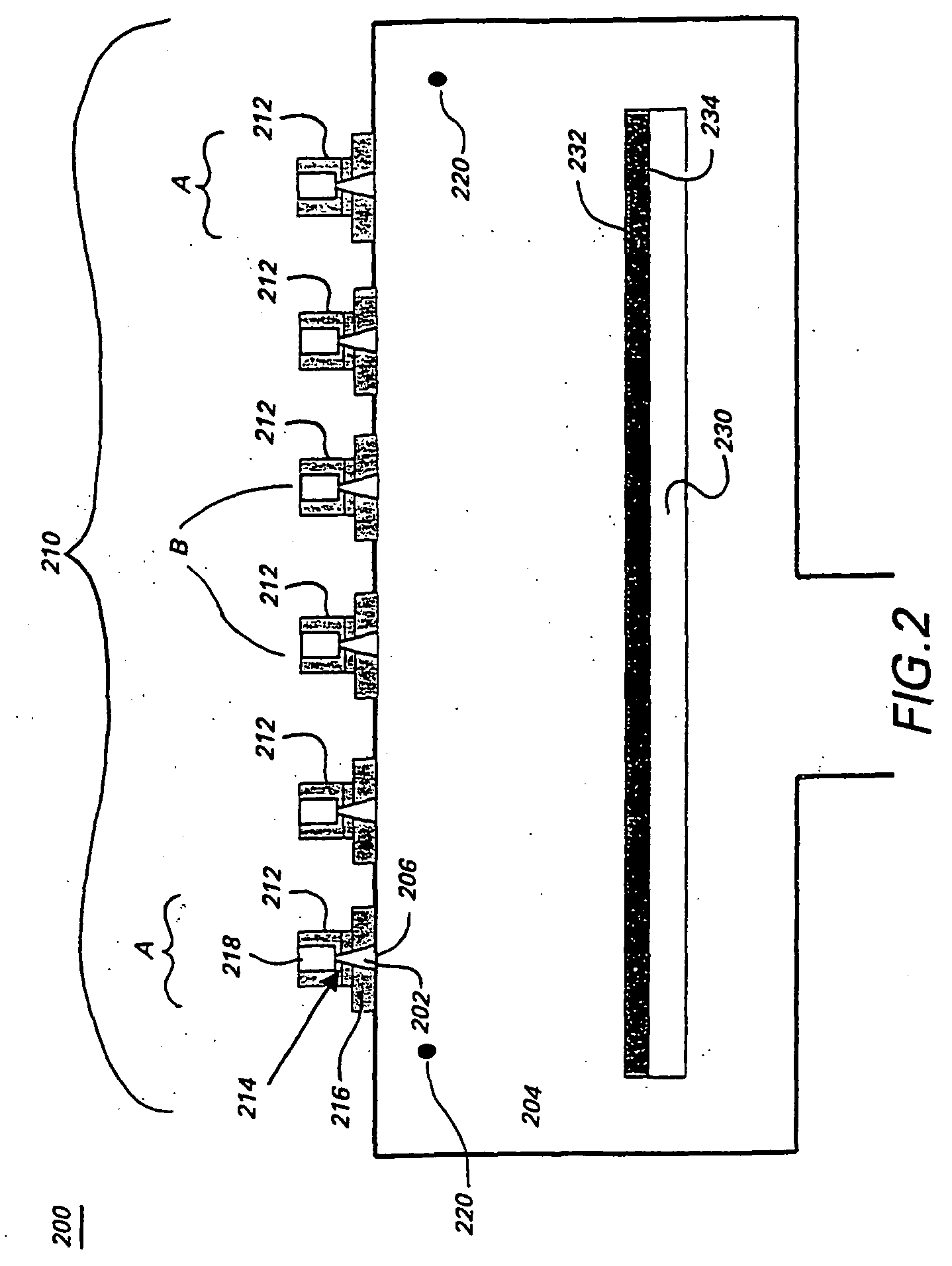
[0006] The present invention meets these and other needs by providing both a method and apparatus for depositing a uniform coating on a large area, planar surface using an array of multiple plasma sources and a common precursor—or reactant gas—injector. By providing the reactant gas (or gases) to the multiple plasma sources through a single delivery system, a uniform flow of reactant gas to each of the multiple plasmas can be easily maintained.

Problems solved by technology

When scaling plasma deposition technology up to coat surfaces having larger dimensions, however, the use of the individual reactant sources and flow controllers may cause significant variability in the coating process and a resulting decrease in coating uniformity.
In addition, as the number of plasma sources used in the coating process increases, the cost to equip each plasma source with an individual delivery system and flow control becomes significant.
An array of multiple plasma sources in which each plasma source has an individual reactant gas injector system is unable to uniformly coat large planar surfaces and is uneconomical.

Method used


Image

  • Apparatus and method for depositing large area coatings on planar surfaces
  • Apparatus and method for depositing large area coatings on planar surfaces
  • Apparatus and method for depositing large area coatings on planar surfaces

Examples


example 1

[0040] Experimental support for the invention is provided by comparing coatings deposited on a flat (i.e., planar) polycarbonate substrate using an array of ETP sources provided with a common reactant gas injection ring of the present invention with coatings that were deposited using an array of ETP sources provided with individual reactant gas injectors. Thickness profiles of amorphous hydrogenated silicon carbide (hereinafter referred to as “a-SiC:H”) coatings obtained with an array of ETP sources in which the vinyltrimethylsilane (VTMS) precursor is delivered to nozzles of the individual ETP sources were compared to thickness profiles of a-SiC:H coatings that were obtained with VTMS using an array of ETP sources provided with the common reactant gas injector ring of the present invention. Thickness profiles of the coatings are shown in FIG. 4. The ratio of the standard deviation of thickness to the mean thickness (sigma / mean) at locations between the ETP sources for the coatings ...

example 2

[0041] The thickness profile of an a-SiC:H coating was obtained with an array of ETP sources in which the octamethylcyclotetrasiloxane (D4) reactant gas was provided by the common reactant gas injector ring of the present invention to the plasmas generated by an array of ETP sources. The thickness profiles of the deposited coating is shown in FIG. 5. The results demonstrate that the deposition with D4 results in a coating with 5% (sigma / mean) inter-ETP source thickness. Thus, the coating obtained by providing reactant gas D4 to the ETP-generated plasmas through the common injector gas ring of the present invention exhibits a high degree of uniformity.

example 3

[0042] Coatings of amorphous hydrogenated silicon oxycarbide (hereinafter referred to as “a-SiOxCy:H”), which can serve as abrasion resistant coatings, are deposited from a mixture of D4 and oxygen (O2) on polycarbonate substrates. In one experiment, the coating was deposited by injecting both D4 and O2 through a single common reactant gas injector ring. In another experiment, the coating was deposited by injecting O2 and D4 through separate common reactant gas injector rings. The coating thickness profiles of the deposited coatings are compared in FIG. 6. The thickness profiles in FIG. 6 are not statistically different, thus demonstrating that individual reactant gases may be provided to the plasmas generated by the plurality of ETP plasmas by either a single common reactant gas injector or separate common gas injectors to yield coatings having a high degree of uniformity.


PUM

PropertyMeasurementUnit
diameteraaaaaaaaaa
temperaturesaaaaaaaaaa
temperatureaaaaaaaaaa

Abstract

A method and apparatus for depositing a uniform coating on a large area, planar surface using an array of multiple plasma sources and a common reactant gas injector. The apparatus includes at least one array of a plurality of plasma sources, wherein each of the plurality of plasma sources includes a cathode, an anode, and an inlet for a non-reactive plasma source gas disposed in a plasma chamber, and a common reactant gas injector disposed in a deposition chamber that contains the substrate. The common reactant gas injector provides a uniform flow of at least one reactant gas to each of the multiple plasmas generated the multiple plasma sources through a single delivery system. The at least one reactant gas reacts with the plurality of plasmas to form a uniform coating on a substrate.

Description

BACKGROUND OF INVENTION [0001] The invention relates to an apparatus and method for depositing a uniform coating on a planar surface. More particularly, the invention relates to a method and apparatus for depositing a uniform coating on a planar surface using multiple plasma sources. Even more particularly, the invention relates to a method and apparatus for depositing a uniform coating on a planar surface by injecting reactant gases through a common injection system into a plurality of plasmas that are generated by multiple expanding thermal plasma sources. [0002] Plasma sources are capable of depositing a large variety of coatings, such as transparent abrasion resistant coatings, transparent UV-filtering coatings, and multi-layer coating packages on a substrate at a high deposition rate. In such deposition processes, a reactant gas interacts with a plasma to form species that are deposited on the substrate. Individual plasma sources, such as expanding thermal plasma (also referred...

Claims


Application Information

Patent Timeline
Patent Type & Authority Applications(United States)
IPC IPC(8): C23C16/32C23C16/40C23C16/50H01J37/32
CPCC23C16/325H01J37/32009C23C16/50C23C16/401
Inventor SCHAEPKENS, MARC
Owner SABIC INNOVATIVE PLASTICS IP BV
Why Eureka
Try Eureka