Method for producing magnetic recording medium and producing apparatus thereof

a technology of magnetic recording medium and producing apparatus, which is applied in the direction of magnetic layer coating, vacuum evaporation coating, coating, etc., can solve the problems of corrosion resistance and inferior environmental resistance of the in-line film formation apparatus described above, and achieve the effects of improving environmental resistance, soft magnetic properties, and high recording density

Inactive Publication Date: 2011-03-10
SHOWA DENKO KK
View PDF5 Cites 13 Cited by
  • Summary
  • Abstract
  • Description
  • Claims
  • Application Information

AI Technical Summary

Benefits of technology

[0083]As described above, according to the invention, it is possible to produce a magnetic recording medium with improved environmental resistance, especially, corrosion resistance in a following manner: when the magnetic recording medium having a magnetic recording pattern formed at least on a magnetic recording layer formed on a surface of the nonmagnetic substrate is produced using an in-line film formation apparatus, each of the chambers has a decompressed atmosphere inside and each of the processes are conducted continuously while being blocked from the ambient air, especially being under a halogen gas-free atmosphere.
[0084]Referring now to the drawings, embodiments of the invention will be described in detail. In the present embodiment, an exemplary method of producing a magnetic recording medium incorporated in a hard disk device by using an in-line film formation apparatus which performs a film formation process while sequentially conveying a nonmagnetic substrate to be subject to film formation through a plurality of chambers will be described.
[0085]As illustrated, for example in FIG. 1, a magnetic recording medium produced in accordance with the invention is configured so that a soft magnetic layer 81, an intermediate layer 82, a magnetic recording layer 83 and a protective layer 84 are laminated in this order on both sides of a nonmagnetic substrate 80. A lubricating film 85 is formed on an outermost surface of the laminated structure. The soft magnetic layer 81, the intermediate layer 82 and the magnetic recording layer 83 altogether constitutes a magnetic layer 810.
[0086]The non-magnetic substrate 80 may be any substrate so long as it is a non-magnetic substrate. Examples thereof include an Al alloy substrate, such as Al—Mg alloy, having Al as a principle component, and usual substrates made of soda glass, aluminosilicate-based glass, crystallized glasses, silicon, titanium, ceramic and various type of resins.
[0087]Among these, an Al alloy substrate, glass substrates, such as crystallized glass or the like, or silicon substrates are preferably used. The average surface roughness (Ra) of these substrates is preferably not more than 1 nm, more preferably not more than 0.5 nm and especially preferably not more than 0.1 nm.
[0088]An in-plane magnetic layer for an in-plane magnetic recording medium or a perpendicular magnetic layer for a perpendicular magnetic recording media can be used as the magnetic layer 810. The perpendicular magnetic layer is especially preferable from the viewpoint of high recording density. The magnetic layer 810 is preferably produced by Co-based alloy. As a magnetic layer 810 for a perpendicular magnetic recording medium, for example, a lamination structure composed of a soft magnetic layer 81, an intermediate layer 82 and a magnetic recording layer 83. Examples of the soft magnetic layer 81 include FeCo alloy (e.g., FeCoB, FeCoSiB, FeCoZr FeCoZrB and FeCoZrBCu), FeTa alloy (e.g., FeTaN and FeTaC) and Co alloy (e.g., CoTaZr, CoZrNB and CoB), which have a soft magnetic property. The intermediate layer 82 may include Ru. The magnetic recording layer 83 may include 60Co-15Cr-15 Pt alloy and 70Co-5Cr-15Pt-10SiO2 alloy. An orientation controlling film including Pt, Pd, NiCr and NiFeCr etc., may be laminated between the soft magnetic layer 81 and the intermediate layer 82. As a magnetic layer 810 for an in-plane magnetic recording medium, for example, a lamination structure composed of a non-magnetic CrMo underlayer and a ferromagnetic CoCrPtTa magnetic layer can be used.

Problems solved by technology

According to the study of the present inventors, however, a discrete track medium produced by the in-line film formation apparatus described above is inferior in environmental resistance, especially corrosion resistance compared with an ordinary magnetic recording medium with no patterned magnetic layer.

Method used


Image

  • Method for producing magnetic recording medium and producing apparatus thereof
  • Method for producing magnetic recording medium and producing apparatus thereof
  • Method for producing magnetic recording medium and producing apparatus thereof

Examples


example 1

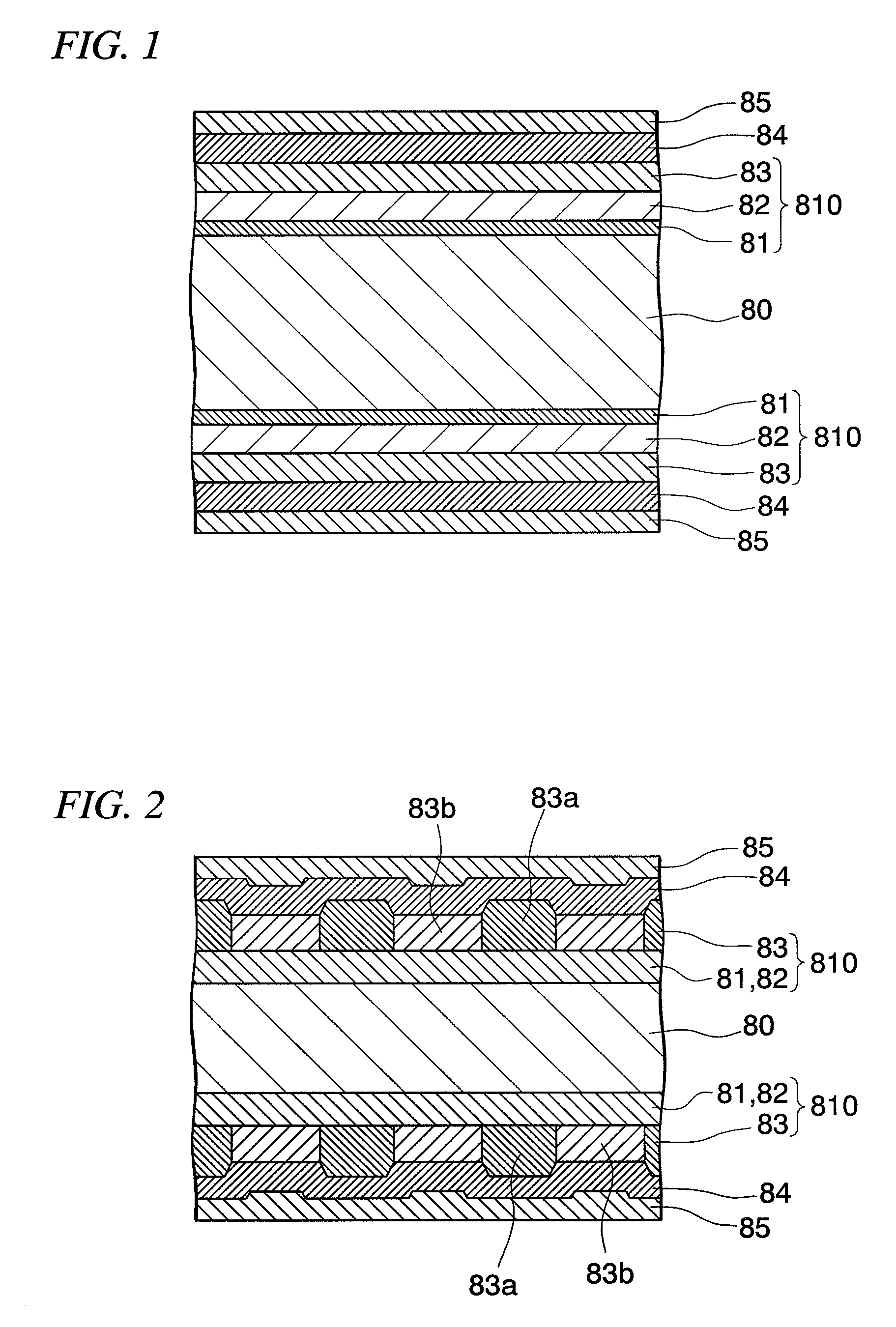
[0177]In Example 1, a glass substrate for the HD was prepared first as a nonmagnetic substrate and placed in a vacuum chamber of an in-line film formation apparatus. The vacuum chamber was evacuated to less than 1.0×10⁻⁵ Pa in advance. The glass substrate used herein was crystallized glass constituted by Li2Si2O5, Al2O3—K2O, Al2O3—K2O, MgO—P2O5 and Sb2O3—ZnO. The glass substrate was formed such that the outer diameter was 65 mm, the inner diameter was 20 mm and the average surface roughness (Ra) was 2 {acute over (Å)}.

[0178]The magnetic layer was formed on the both sides of the glass substrate by laminating FeCoB as the soft magnetic layer, Ru as the intermediate layer and a 70Co-5Cr-15Pt-10SiO2 alloy as the magnetic recording layer by DC sputtering method. The thickness of the soft magnetic layer was 600 {acute over (Å)}, the thickness of the intermediate layer was 100 {acute over (Å)} and the thickness of the magnetic recording layer was 150 {acute over (Å)}.

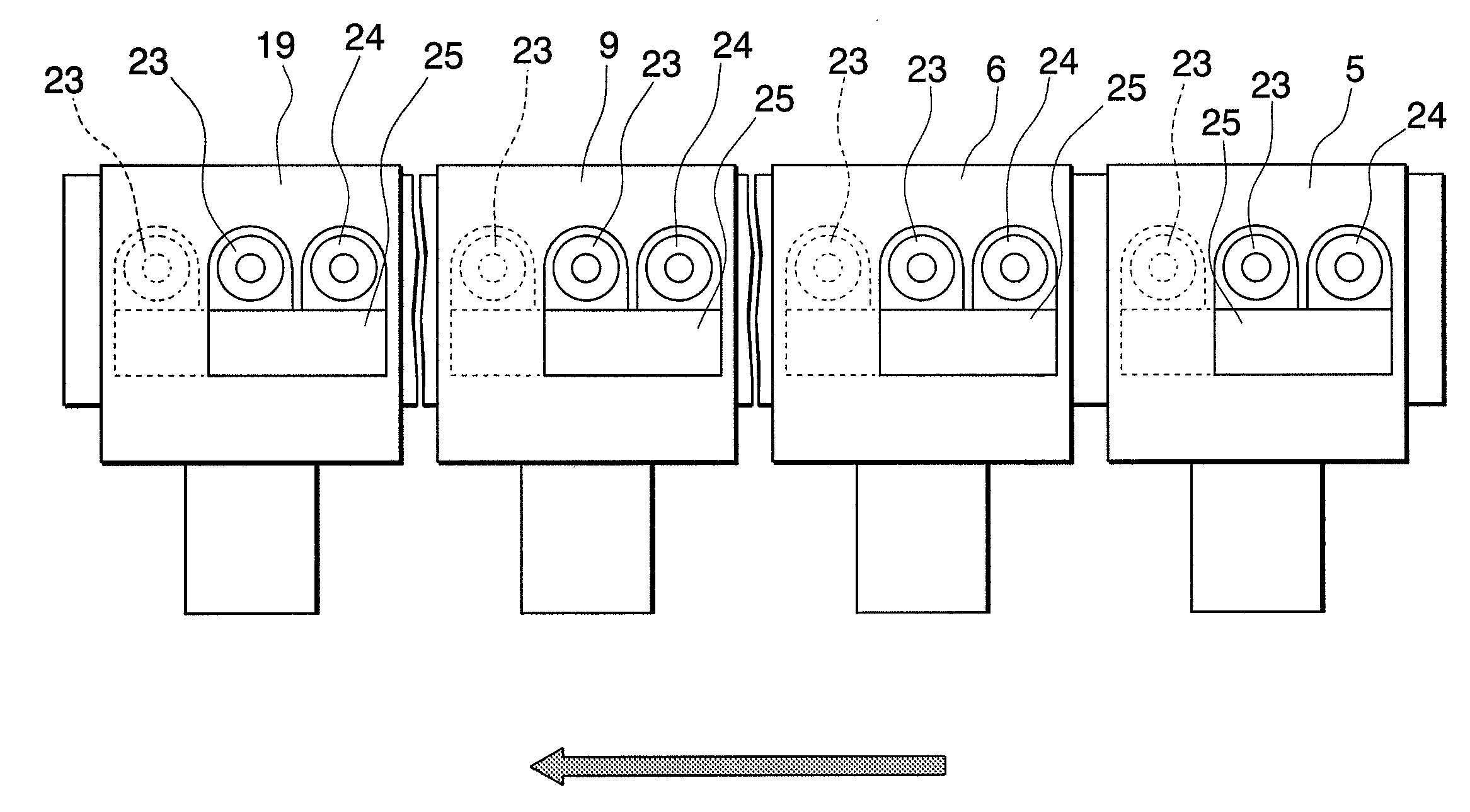
[0179]Next, the mask l...

example 2

[0193]In Example 2, a magnetic recording medium was produced in the same manner as in Example 1 except that CF4 gas was used instead of an O2 gas for etching the Ta layer in the processing chambers 16 and 18.

(Evaluation of Corrosion Resistance)

[0194]Corrosion resistance was evaluated for the magnetic recording media of Examples 1 and 2 and Comparative Example 1. For the evaluation, all of the magnetic recording media was kept in an ambient air environment with a temperature of 80° C. and a humidity of 85% for 96 hours. The number of the corrosion spots having a diameter larger than 5 microns φ developed on the surface of the magnetic recording medium was counted.

[0195]A 3% nitric acid solution was dropped at five points (i.e., 100 microliters / point) and pure water are dropped at five points (i.e., 100 microliters / point) on the surface of each of the magnetic recording media. The magnetic recording medium was left for one hour and then collected. The amount of Co contained was measur...


PUM

PropertyMeasurementUnit
Raaaaaaaaaaa
Raaaaaaaaaaa
Raaaaaaaaaaa

Abstract

Provided are a method of producing a magnetic recording medium with improved environmental resistance, especially, corrosion resistance and an apparatus used therefor. In producing a magnetic recording medium having a magnetic recording pattern on a magnetic recording layer formed on at least a surface of a nonmagnetic substrate using an in-line film formation apparatus, the method comprising: mounting a nonmagnetic substrate on the carrier, the nonmagnetic substrate having at least the magnetic recording layer and a mask layer corresponding to the magnetic recording pattern laminated thereon in this order; forming the magnetic recording pattern by having areas of the magnetic recording layer that are not covered with the mask layer subjected to a reactive plasma treatment or an ion irradiation treatment; removing the mask layer from the magnetic recording layer; and removing the nonmagnetic substrate from the carrier, wherein each of the chambers has a decompressed atmosphere inside while the carrier passes through each of the chambers and each of the processes are conducted continuously while being blocked from the ambient air.

Description

BACKGROUND OF THE INVENTION[0001]1. Field of the Invention[0002]The present invention relates to a method of producing a magnetic recording medium used for a hard disk device and to an apparatus used therefor. More particularly, the invention relates to a method of producing, for example, a discrete track medium and a patterned medium which has a magnetically-isolated magnetic recording area, and to an apparatus for implementing the method.[0003]Priority is claimed on Japanese Patent Application No. 2008-286467, filed Nov. 7, 2008, the content of which is incorporated herein by reference.[0004]2. Background Art[0005]In recent years, magnetic recorders such as magnetic disk units, flexible disk units, and magnetic tape units have been used over a remarkably wider range of applications, and play more important roles. With this trend, an attempt is being made to highly increase the recording density of magnetic recording media for use in such recorders. In particular, the surface recor...

Claims


Application Information

Patent Timeline
Patent Type & Authority Applications(United States)
IPC IPC(8): B05D5/00B05C13/00
CPCC23C14/042G11B5/855C23C14/568C23C14/34
Inventor FUKUSHIMA, MASATOISHIBASHI, SHINICHIYAMANE, AKIRA
Owner SHOWA DENKO KK
Why Eureka
Try Eureka