
Plasma processing in a capacitively-coupled reactor with trapezoidal-waveform excitation

a capacitively coupled reactor and trapezoidal waveform technology, which is applied in the direction of plasma technique, chemical vapor deposition coating, coating, etc., can solve the problems of complex shape of ion energy distribution function (iedf) in conventional sinusoidally excited reactors, inability to control, and limited processing rate, so as to enhance the supply of deposition precursors and reduce deposition

Active Publication Date: 2013-05-30
ECOLE POLYTECHNIQUE +1
View PDF3 Cites 11 Cited by
  • Summary
  • Abstract
  • Description
  • Claims
  • Application Information

AI Technical Summary

Benefits of technology

The present invention provides a technique for controlling plasma density and ion energy during a chemical vapor deposition process. This allows for the highest possible particle fluxes to the substrate with the lowest ion energies, resulting in optimal process quality. This technique can be applied in both plasma deposition and etch processes, leading to better performance in a variety of applications. The method also allows for a different process regime in certain processes, such as lower pressure, less dilute gas mixtures, and higher plasma density, which have been shown to increase deposition rates and reduce dust formation. The substrate can be placed on either the powered or unpowered electrode, and the trapezoidal waveform can be used to adjust the growth of thin films between amorphous and nano- or micro-crystalline growth.

Problems solved by technology

In many applications, such as PECVD of silicon thin films, excessive ion energy damages the substrate or deposited film, so that only low voltages can be used, resulting in limited processing rates.
Furthermore, the shape of the ion energy distribution function (IEDF) in conventional sinusoidally excited reactors is complex, typically saddle-shaped, and cannot be controlled.
Further problems occur in large area high-frequency reactors due to standing wave effects, causing non-uniform processing across the wafer.

Method used


Image

  • Plasma processing in a capacitively-coupled reactor with trapezoidal-waveform excitation
  • Plasma processing in a capacitively-coupled reactor with trapezoidal-waveform excitation
  • Plasma processing in a capacitively-coupled reactor with trapezoidal-waveform excitation

Examples


Embodiment Construction

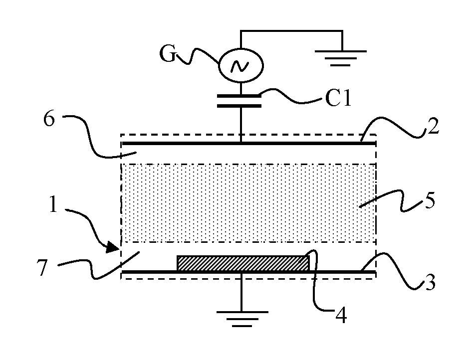
[0047]A simplified schematic of a capacitively-coupled plasma reactor, shown in FIG. 1, comprises a processing chamber 1, a powered electrode 2, and an unpowered electrode 3. Radio-frequency power from a generator G is applied through a blocking capacitor C1 to the powered electrode 2. The substrate 4 to be processed can be placed either on the powered electrode 2 or on the grounded or unpowered electrode 3. Plasma 5 is generated inside the volume of processing chamber 1 between the powered electrode 2 and the substrate 4.

[0048]In all plasma reactors so-called sheaths 6 and 7 form between the bulk plasma and all the surfaces surrounding it (the electrodes, substrates and processing chamber walls). Sheaths have a high impedance, which is principally capacitive. It is the sheath impedance that limits the current flowing through the plasma 5, and therefore determines the power absorbed by the electrons. The majority of the RF voltage applied across the electrodes is divided between the...


PUM

PropertyMeasurementUnit
frequencyaaaaaaaaaa
voltagesaaaaaaaaaa
diameteraaaaaaaaaa

Abstract

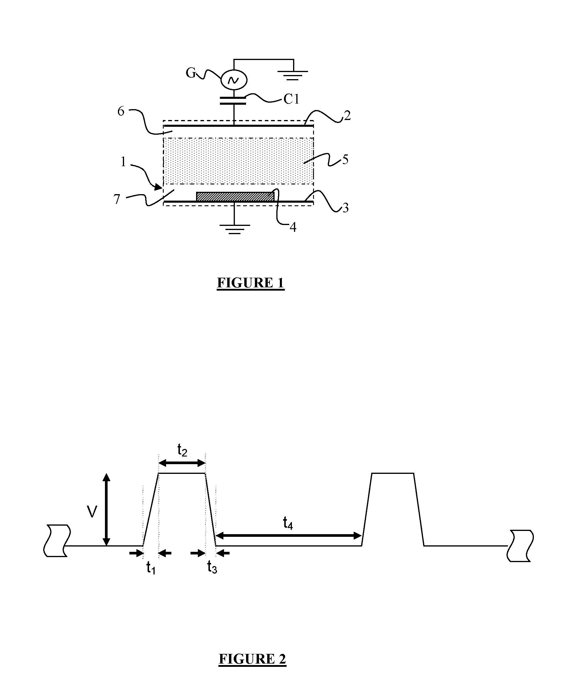
A method is provided for exciting at least one electrode of a capacitively coupled reactive plasma reactor containing a substrate. The electrode is excited by applying a RF voltage with a trapezoidal waveform comprising a ramp-up, a high plateau, a ramp-down and a low plateau. The plasma density can be controlled by adjusting the duration of the ramp-up, the duration of the ramp-down, the amplitude and the repetition rate of the trapezoidal waveform. The ion energy distribution function at the substrate can be controlled by adjusting the amplitude and the relative duration between the high plateau and the low plateau of the trapezoidal waveform.

Description

BACKGROUND OF THE INVENTION[0001]A method and system are disclosed for exciting at least one electrode of a capacitively coupled reactive plasma reactor containing a substrate.[0002]The present invention may advantageously be applied to:[0003]Plasma-enhanced Chemical Vapour Deposition (PECVD) of thin films, for example of amorphous, micro- and nano-crystalline alloy of silicon and / or germanium and / or carbon for photovoltaic solar cell manufacture; also deposition of other thin films such as SiO2, Si3N4 etc for flat-panel display and integrated circuit manufacture;[0004]Plasma etching of thin films, including Si, SiO2, Si3N4, metals etc for FPD manufacture, integrated circuit manufacture, photonic device manufacture; and[0005]Other plasma surface modification processes such as ion implantation, surface modification, hardening etc . . .[0006]In general, parallel-plate reactors excited by capacitively-coupled radio-frequency (RF) power, with frequency from 0.1 to 200 MHz for example, a...

Claims


Application Information

Patent Timeline
Patent Type & Authority Applications(United States)
IPC IPC(8): C23C16/509
CPCH01J37/32091C23C16/509H01J2237/3348H01J37/00H01J37/32
Inventor BOOTH, JEAN-PAULJOHNSON, ERIK
Owner ECOLE POLYTECHNIQUE
Learn More