Battery separator
- Summary
- Abstract
- Description
- Claims
- Application Information
AI Technical Summary
Benefits of technology
Problems solved by technology
Method used
Image

Examples
example 1
A battery separator with a bismuth trapping layer was prepared as follows.
Bismuth powder (−325 mesh, i.e. <45 μm particle size) was dispersed in a poly(acrylic acid) / ethanol / water solution with a high speed disperser. The loading of the bismuth was targeted to result in a composition that was 20 percent by volume bismuth powder and 80 percent by volume polymer.
The viscous mixture was coated onto a silicone-coated Mylar release liner using a 25 mil wet thickness draw-down applicator.
The material was dried under ambient conditions and removed from the release liner to yield a 60 micron, free-standing film.
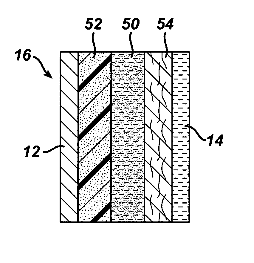
The trapping layer as prepared above was used to form a multi-layer separator. The trapping layer was located in the middle of the separator, with a selective membrane at one end and a non-woven layer at the other end. The separator was assembled as follows.
A 54 micron poly(vinyl alcohol)-based non-woven fabric was wetted with water.
The bismuth-poly(acrylic acid) fi...
example 2
A battery separator with a tin trapping layer was prepared as follows.
Tin powder (−325 mesh, i.e. <45 μm particle size) was dispersed in a poly(acrylic acid) / ethanol / water solution with a high speed disperser. The loading of the tin was targeted to result in a composition that was 20 percent by volume tin powder and 80 percent by volume polymer.
The viscous mixture was coated onto a silicone-coated release liner using a 25 mil wet thickness draw-down applicator.
The material was dried under ambient conditions and removed from the release liner to yield a 60 micron, free-standing film.
The trapping layer as prepared above was used to form a multi-layer separator. The trapping layer was located in the middle of the separator, with a selective membrane at one end and a non-woven layer at the other end. The separator was assembled as follows.
A 54 micron poly(vinyl alcohol)-based non-woven fabric was wetted with water.
The tin-poly(acrylic acid) film (the trapping layer) wa...
example 3
A battery including a multilayer separator was prepared as follows.
Preparation of the Separator
A battery separator with a trapping layer that included both a bismuth-containing sub-layer and a zirconia (zirconium dioxide)-containing sub-layer was prepared according to the following procedure.
First, a dry film including bismuth was prepared. Using a high shear laboratory mixer (from Silverson L4RT-A) at 5000 rpm, 25 grams of Carbopol 934 were slowly added to 375 grams of ethanol. Next, 100 grams of Glascol E11 were slowly added to the mixture, with continued mixing, until a homogeneous viscous solution was obtained. Then, 150 grams of bismuth metal (−325 mesh, 99.5% metals basis) were slowly added to the mixture, and mixing was continued until the mixture was homogeneous. The viscous suspension was then coated in 6″ wide strips onto a silicone-coated Mylar release liner, using a film applicator. The result was a dry film with a thickness of 90 microns.
In a separate process t...
PUM
 Abstract
Description
Claims
Application Information
 - Generate Ideas
- Intellectual Property
- Life Sciences
- Materials
- Tech Scout
- Unparalleled Data Quality
- Higher Quality Content
- 60% Fewer Hallucinations
Browse by: Latest US Patents, China's latest patents, Technical Efficacy Thesaurus, Application Domain, Technology Topic, Popular Technical Reports.
© 2025 PatSnap. All rights reserved.Legal|Privacy policy|Modern Slavery Act Transparency Statement|Sitemap|About US| Contact US: help@patsnap.com