Humidity sensor element, device and method for manufacturing thereof

a technology of humidity sensor and element, which is applied in the direction of piezoelectric/electrostrictive transducers, instruments, and mechanical means, etc., can solve the problems of inconvenient long-term use of film, conventional restrictions on application of humidity sensor, and damage to film, etc., to achieve better measuring ability, high linear accuracy, and high accuracy

Active Publication Date: 2005-04-21
IND TECH RES INST
View PDF4 Cites 37 Cited by
  • Summary
  • Abstract
  • Description
  • Claims
  • Application Information

AI Technical Summary

Benefits of technology

[0036] The humidity sensor element disclosed in the present invention is coated with a nanocomposite containing carbon nanotube and perfluorinated polymer having acid functional group as humidity sensing film, offers high linear accuracy even at low humidity, superior to that of prior technologies. Accordingly, the invention provides a humidity sensor element with higher accuracy and better measuring ability at low humidity.

Problems solved by technology

However the first type of films exhibits the disadvantages of having narrow humidity measuring range that its resistance change is remarkable in high humidity environments, but relatively unapparent in low humidity environments.
Besides having the problem of narrow humidity measuring range, the second type of films is not suitable for long-term use at high humidity environments, because the electrolytes contained therein can be diluted and lost due to excessive moisture adsorption.
The third type of films has the problem that the film may be damaged because of rising temperature, as such the humidity detection may be influenced.
The applications of humidity sensor are conventionally restricted by their non-linearity at high (>90 %RH) and low (<30 %RH) humidity environments.
Okada et al. employed Nafion (Ag) film with detection range of 1000-15000 ppmv, but the linear accuracy of the sensor is not satisfactory.
The presence of moisture, a kind of residual gas in the process, would cause distinct and adverse changes to the properties of metals and semiconductor films, for example, blocking the optical components or corroding the mechanical components.
But few of the currently available humidity sensors can accurately detect low-level moisture as constrained by the property of the material used.

Method used


Image

  • Humidity sensor element, device and method for manufacturing thereof
  • Humidity sensor element, device and method for manufacturing thereof
  • Humidity sensor element, device and method for manufacturing thereof

Examples


examples

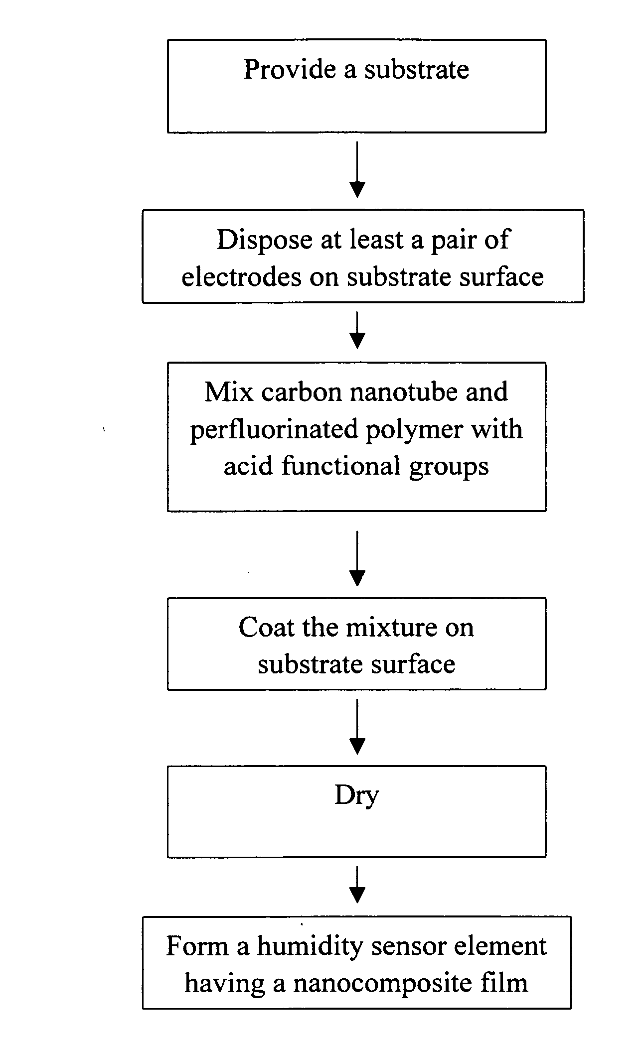
(A) Manufacturing of Humidity Sensor Element

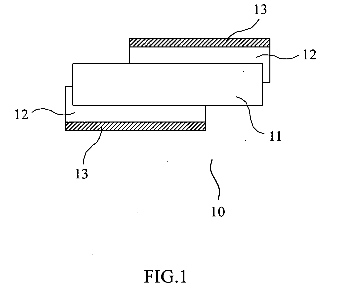
[0054] Take 0.001 g of single-walled carbon nanotube (CNT, supplied by Carbon Technology, Inc., CAS Number: 7782-42-5) and 5 g of 0.5 wt. % Nafion (dissolved in the mixture of lower fatty alcohol and water, purchased from Aldrich, USA, which is perfluorinated ionic polymer containing small amount of sulphonic group or carboxyl group), and mix them thoroughly to form CNT / Nafion mixture. Drip the mixture on the gold electrodes of quartz crystal (AT-cut quartz crystal), spin coat at the speed of 1000 rpm for 3 minutes, and dry to obtain a humidity sensor element coated with CNT / Nafion nanocomposite film.

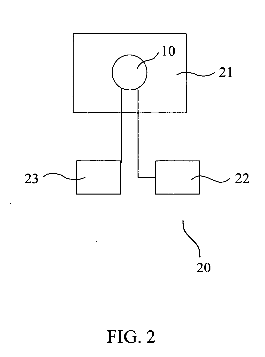
(B) Experimental Apparatus

[0055] As shown in FIG. 4 which illustrates an apparatus for measuring low humidity in this example, the flow of gas produced by standard humidity generator 30 is controlled by flow controller 31, and the gas is heated by piping wrapped with heating tape 32 and enters into the testing chamber 21 after passing thr...


PUM

PropertyMeasurementUnit
RHaaaaaaaaaa
RHaaaaaaaaaa
RHaaaaaaaaaa

Abstract

A humidity sensor element, a humidity sensor device and a method for manufacturing thereof are provided. The humidity sensor element includes a substrate having a nanocomposite film as sensing material, wherein said nanocomposite film consists of carbon nanotube/perfluorinated polymer with acid functional groups in weight ratio of 0.01-20; and at least a pair of electrodes, which contact with the sensing material at one or both side(s). The nanocomposite film increases the sensitivity of humidity sensor element such that even an infinitesimal amount of moisture can be detected with minimum detection limit of 15.76 ppmv

Description

BACKGROUND OF THE INVENTION [0001] 1. Field of the Invention [0002] The present invention discloses a humidity sensor element, device and a method for manufacturing thereof. The humidity sensor element comprises a substrate having a nanocomposite film as sensing material, wherein said nanocomposite film contains carbon nanotube / perfluorinated polymer with acid functional groups; and at least a pair of electrodes, which contact with the sensing material at one or both side(s). The nanocomposite film is highly sensitive in detecting infinitesimal amount of moisture. [0003] 2. Description of Related Art [0004] A sensor detects a physical or chemical variation in the outside environment, such as temperature, pressure or humidity through its sensing element, and converts the variation through a transduction element into electrical signals that may be transmitted and measured. It works by changing the resistance, capacitance, or oscillation frequency in piezoelectric effect. In the applic...

Claims


Application Information

Patent Timeline
Patent Type & Authority Applications(United States)
IPC IPC(8): G01N27/00G01N29/02
CPCB82Y30/00G01N29/022G01N2291/014G01N2291/0255Y10T29/49002G01N2291/02845G01N2291/0426Y10T29/42Y10T29/49007G01N2291/0256
Inventor CHEN, HUI WENWU, REN JANGSUN, YI LUSU, PI GUEY
Owner IND TECH RES INST
Why Eureka
Try Eureka