Micro magnetic non-latching switches and methods of making same

a non-latching switch, micro magnetic technology, applied in the direction of electromagnetic relays, electrical apparatus, electrical relay details, etc., can solve the problems of low production efficiency, difficult manufacturing and integration, and deformation or breakage of the spring required by conventional micro-magnetic relays, and achieves good performance at high frequencies and simple fabrication.

Inactive Publication Date: 2005-04-21
SCHNEIDER ELECTRIC IND SAS
View PDF33 Cites 12 Cited by
  • Summary
  • Abstract
  • Description
  • Claims
  • Application Information

AI Technical Summary

Benefits of technology

[0009] The non-latching micro-magnetic switches of the present invention can be used in a plethora of products including household and industrial appliances, consumer electronics, military hardware, medical devices, vehicles of all types, just to name a few broad categories of goods. The non-latching micro-magnetic switches of the present invention have the advantages of compactness, simplicity of fabrication, and have good performance at high frequencies.

Problems solved by technology

Such relays typically exhibit a number of marked disadvantages, such as they are bulky in size, heavy, slow, expensive, and difficult to manufacture and integrate.
Also, the spring required by conventional micro-magnetic relays may degrade or break over time.
One drawback is that the relay must consume power from the electromagnet to maintain at least one of the output states.
Moreover, the power required to generate the opposing field is significant, thus making the relay less desirable for use in space, portable electronics, and other applications that demand low power consumption.

Method used


Image

  • Micro magnetic non-latching switches and methods of making same
  • Micro magnetic non-latching switches and methods of making same
  • Micro magnetic non-latching switches and methods of making same

Examples


Embodiment Construction

[0020] It should be appreciated that the particular implementations shown and described herein are examples of the invention, and are not intended to otherwise limit the scope of the present invention in any way. Indeed, for the sake of brevity, conventional electronics, manufacturing, MEMS technologies, and other functional aspects of the systems (and components of the individual operating components of the systems) may not be described in detail herein. Furthermore, for purposes of brevity, the invention is frequently described herein as pertaining to micro-machined switches for use in electrical or electronic systems. It should be appreciated that many other manufacturing techniques could be used to create the switches described herein, and that the techniques described herein could be used in mechanical switches, optical switches, or any other switching device. Further, the techniques would be suitable for application in electrical systems, optical systems, consumer electronics,...


PUM


Abstract

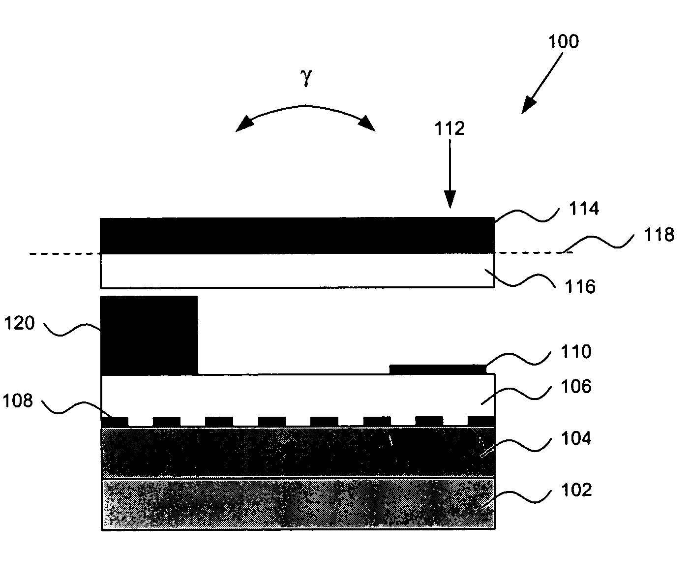
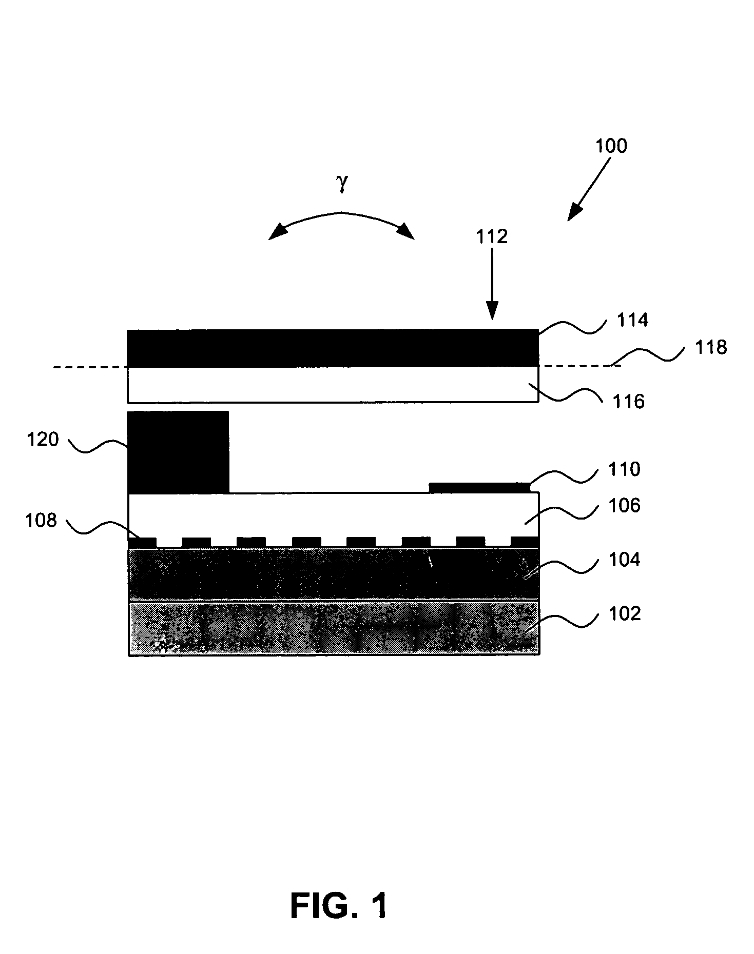
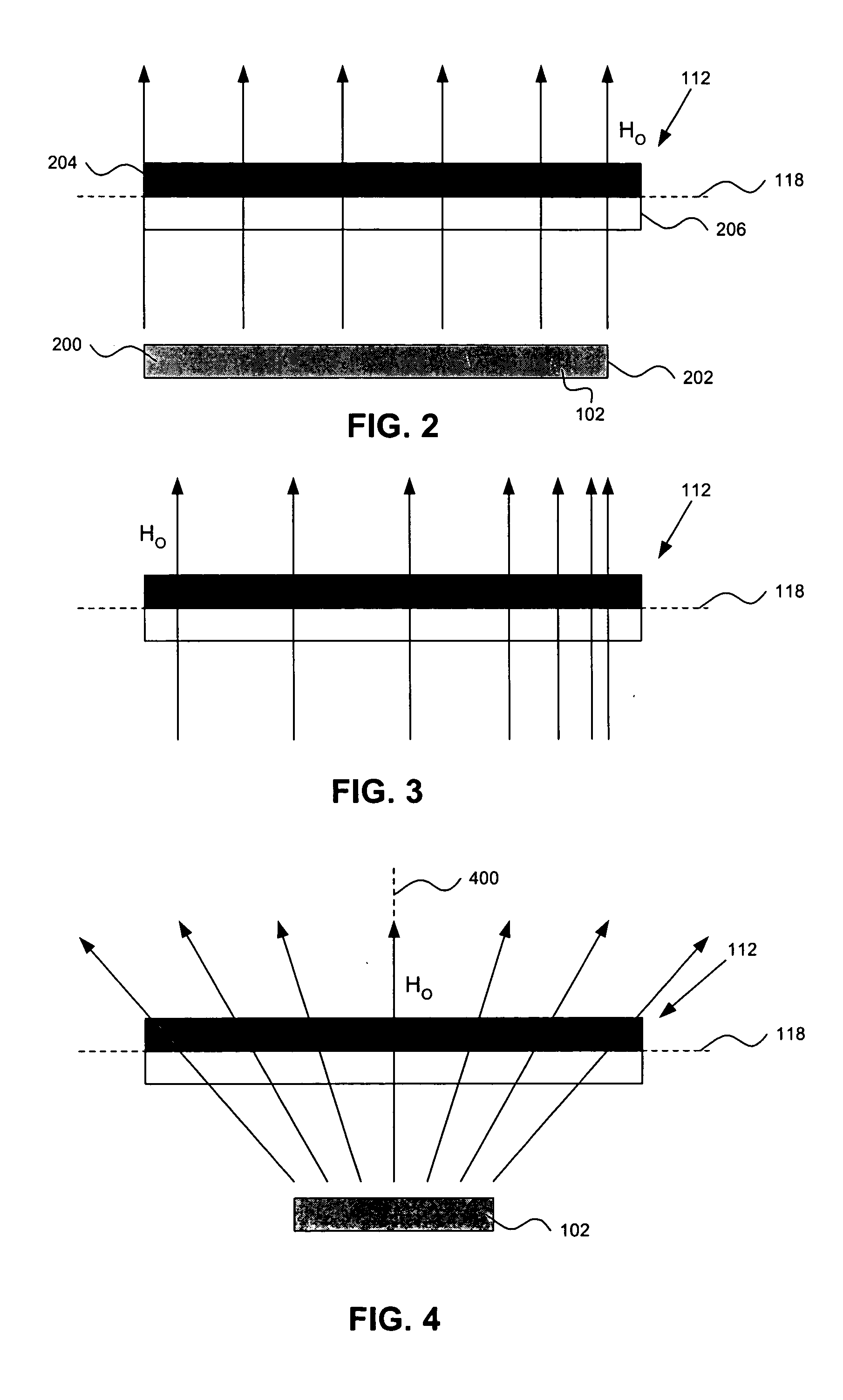
A micro magnetic switch includes a reference plane and a magnet located proximate to a supporting structure. The magnet produces a first magnetic field with uniformly spaced field lines approximately orthogonal to the reference plane, symmetrically spaced about a central axis, or non-uniformly spaced fields approximately orthogonal to the reference plane. The switch also includes a cantilever supported by the support structure. The cantilever has an axis of rotation lying in the reference plane and has magnetic material that makes the cantilever sensitive to the first magnetic field, such that the cantilever is configured to rotate about the axis of rotation between first and second states. The switch further includes a conductor located proximate to the supporting structure and the cantilever. The conductor is configured to conduct a current. The current produces a second magnetic field having a component approximately parallel to the reference plane and approximately perpendicular to the rotational axis of the cantilever, which causes the cantilever to switch between the first and second states. The switch still further includes a stopping device located proximate to the supporting structure. The stopping device is operable to stop the cantilever from rotating about the axis of symmetry beyond a point at which a longitudinal axis of the cantilever is approximately parallel to a longitudinal axis of the magnet.

Description

BACKGROUND OF THE INVENTION [0001] 1. Field of the Invention [0002] The present invention relates to non-latching electronic switches. More specifically, the present invention relates to a non-latching micro magnetic switch. [0003] 1. Background Art [0004] Switches are typically electrically controlled two-state devices that open and close contacts to effect operation of devices in an electrical or optical circuit. Relays, for example, typically function as switches that activate or de-activate portions of electrical, optical, or other devices. Relays are commonly used in many applications including telecommunications, radio frequency (RF) communications, portable electronics, consumer and industrial electronics, aerospace, and other systems. More recently, optical switches implemented with relays (also referred to as “optical relays” or simply “relays” herein) have been used to switch optical signals (such as those in optical communication systems) from one path to another. [0005] ...

Claims


Application Information

Patent Timeline
Patent Type & Authority Applications(United States)
IPC IPC(8): H01H50/00H01H51/22
CPCH01H50/005
Inventor SHEN, JUNRUAN, MEICHUN
Owner SCHNEIDER ELECTRIC IND SAS
Why Eureka
Try Eureka