Device for the treatment of hydrocephalus

a hydrocephalus and device technology, applied in the direction of suction devices, intravenous devices, wound drains, etc., can solve the problems of ventricular wall collapse, excessive csf drainage, and the principle of shunting is not an ideal solution, so as to avoid complications

Inactive Publication Date: 2005-04-21
SINU SHUNT
View PDF7 Cites 9 Cited by
  • Summary
  • Abstract
  • Description
  • Claims
  • Application Information

AI Technical Summary

Benefits of technology

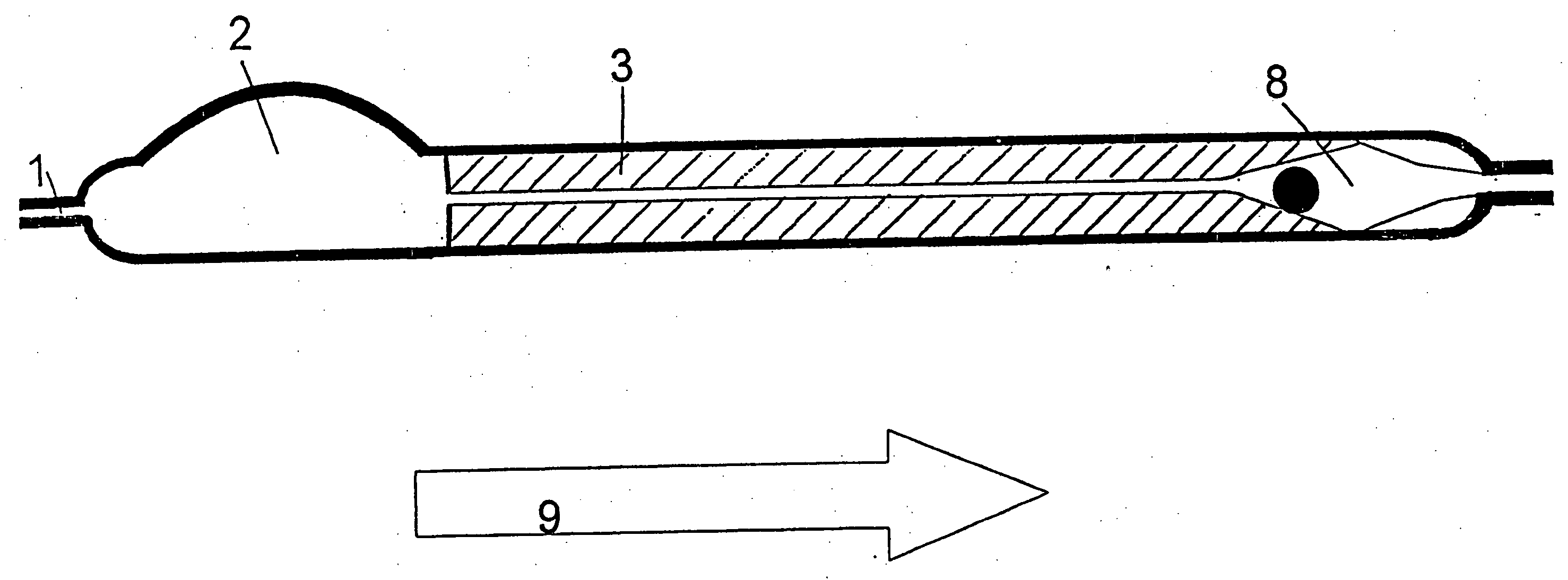
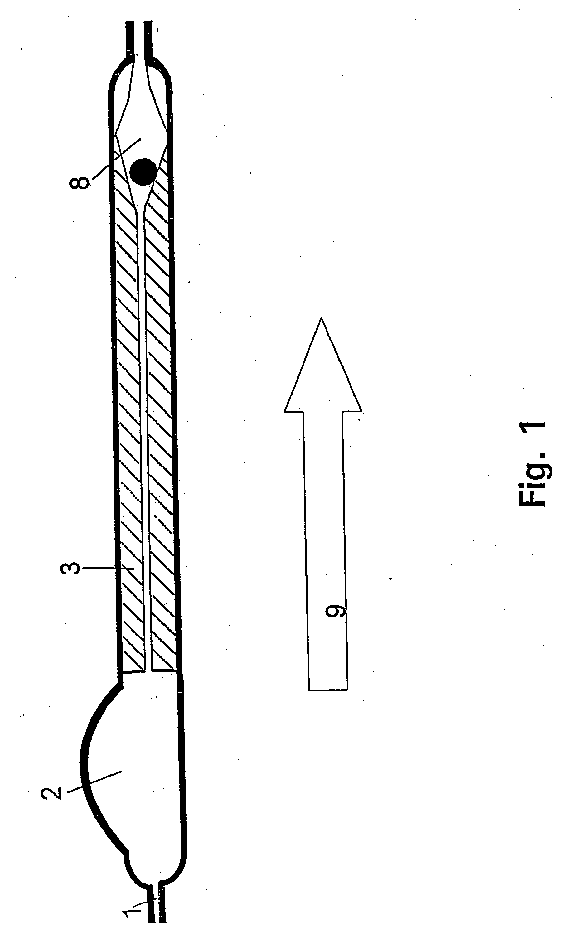
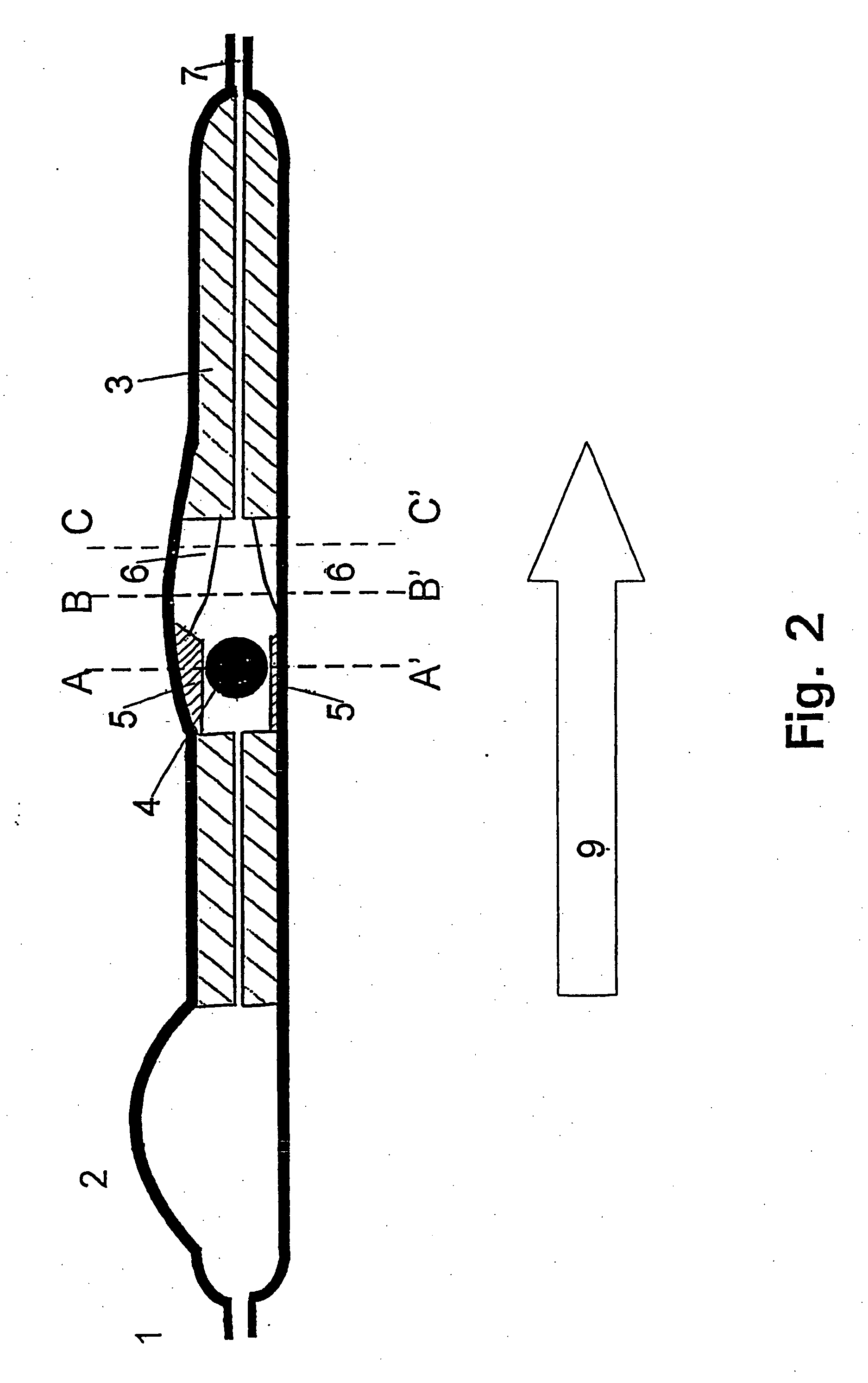
[0013] The device for treatment of hydrocephalus of the invention leads-the CSF from the ventricles to the sagittal sinus beneath the sagittal suture. The present invention thus provides a CSF shunt system that treats the hydrocephalus by bypassing the pathological obstruction, but diverts the CSF into its normal resorption site, and the pressure difference over the CSF shunt system is similar to the physiological pressure differences between the ventricles and the resorption site, thus regulating the CSF flow to be within the normal range and avoiding complications due to hyper drainage. Where appropriate, the present invention also relates to a method of treating hydrocephalus by use of the cerebrospinal fluid shunt system of the invention.

Problems solved by technology

Clinical experience has proven that this principle of shunting is not an ideal solution.
Sudden rises of the ICP, e.g. due to change of position, physical exercise, or pathological pressure waves result in excessive CSF drainage.
Several reports in the literature (Aschoff et al., 1995) point at problems due to this hyperdrainage, and especially the pronounced narrowing of the ventricles has been pointed out to be the main factor leading to malfunctioning of the implanted shunting device.
The reason is that the ventricular walls may collapse around the ventricular CSF shunt device, and particles (cells, debris) may intrude into the shunt device.
An effect of these different drain designs on the complication rates of shunts has not been proven.
One of the problems not addressed in this study is overdrainage due to the fact that the used valve is not flow-restricting.
Essentially, this patent relates to a draining system aiming at avoiding obstruction due to clotting of the draining system and is not flow-regulating.

Method used


Image

  • Device for the treatment of hydrocephalus
  • Device for the treatment of hydrocephalus
  • Device for the treatment of hydrocephalus

Examples


Embodiment Construction

[0024] In normal conditions the CSF is produced in the chorioid plexus in the ventricles. It flows through the ventricles, aqueduct and basal cisterns over the cerebral surface to the arachnoid villi, from where the CSF is absorbed into the sagittal sinus.

[0025] From measurements in 333 patients (Brgesen and Gjerris 1987) and 52 normal humans (Albeck, Brgesen et al. (submitted for publication)) it has been possible to establish the relationship between CSF production rate (FR), intracranial pressure (ICP), pressure in the sagittal sinus (Pss) and the resistance to outflow of CSF (Rout):

ICP=FR*Rout+Pss

[0026] The relation between the intracranial pressure and the formation rate is linear, and the production rate measured was found to be 0.3 ml / min. (Brgesen and Gjerris 1989).

[0027] The detailed knowledge on CSF-dynamics, obtained in the laboratories at the Department of Neurosurgery, Rigshospitalet, Copenhagen, Denmark, has provided the necessary data which could make it possible ...


PUM


Abstract

A cerebrospinal fluid shunt system comprises a brain ventricular catheter for insertion into the brain ventricle so as to drain cerebrospinal fluid from the brain ventricle. The system also comprises a sinus sagittalis catheter for insertion into the sinus sagittalis for feeding the cerebrospinal fluid into sinus sagittalis. A shunt main body is connected at one end thereof to the brain ventricle catheter and at another end thereof to the sinus sagittalis catheter. The shunt main body can provide fluidic communication between the brain ventricle catheter and the sinus sagittalis catheter. The system further comprises a tubular flow passage restricting member defined within the shunt main body. The tubular flow passage restricting member defines a resistance to flow of 8-12 mm Hg / ml / min.

Description

[0001] The present invention relates to a cerebrospinal fluid shunt system for shunting cerebrospinal fluid from the brain ventricles to sinus sagittalis. GENERAL BACKGROUND [0002] Cerebrospinal fluid is formed in the ventricular system irrespective of the intracranial pressure (ICP). The formation rate is constant, with a range of 0.3-0.4 ml / min. (Brgesen and Gjerris 1987). Hydrocephalus, i.e. a pathological increase in the amount of intracranially located cerebrospinal fluid, arise when the outflow of the cerebrospinal fluid is obstructed leading to an increase in the intracranial pressure and in the amount of intracranially located cerebrospinal fluid. The obstruction may be localized in the aqueduct or the IV ventricle or in the normal resorption sites in villi arachnoidales in connection with the sagittal sinus. Pathoanatomically, hydrocephalus is divided in communicating or non-communicating hydrocephalus dependent whether there is passage between the ventricular system and si...

Claims


Application Information

Patent Timeline
Patent Type & Authority Applications(United States)
IPC IPC(8): A61M27/00A61M1/00
CPCA61M27/006
Inventor BORGESEN, SVEND ERIK
Owner SINU SHUNT
Why Eureka
Try Eureka