Indwelling device

a technology of indwelling devices and stents, which is applied in the field of indwelling medical devices, can solve the problems of further infection around the device and undesirable blood clot formation, and achieve the effects of enhancing sliding, preventing penetration of contamination, and enhancing relative sliding

Inactive Publication Date: 2005-04-21
OSTFELD ISHAY +1
View PDF19 Cites 14 Cited by
  • Summary
  • Abstract
  • Description
  • Claims
  • Application Information

AI Technical Summary

Benefits of technology

[0023] The space between the device and a cover or between two adjacent covers may contain material to reinforce the attachment or to enhance relative sliding. The material may repel deposits, and / or contain pharmaceutically-active agents, including but not limited to anti-microbial agents such as antibiotics. The interface material can be the same or different, for each pair of adjacent members. For example, mineral oil may be present to enhance sliding and prevent penetration of contamination between the members.
[0024] In a particularly preferred embodiment of the device of the present invention, sealing elements are present at the distal and / or proximal extremities of the covered device. The presence of these sealing elements prevents the ingress of liquids such as blood, urine, tissue fluid and so on into the space between pairs of adjacently-disposed covers or into the space between the innermost cover and the external surface of the medical device itself. In another aspect, the present invention is also directed to indwelling medical devices having an inner or luminal surface, at least a portion of which is protected by either one manually detachable cover or a stack of two more sequentially detachable covers. This particular embodiment of the device of the invention is particularly suitable for use in applications where it is desirable to prevent the formation and growth of blood clots on the luminal surface of indwelling devices such as venous and arterial catheters. During insertion, the cover is attached to the surface so as to prevent relative movement of the surface and the cover. This allows the integrity of the device and cover to be maintained during insertion. Once the covered internal device (e.g. internal surface of a catheter or drain) has been inserted into the desired operating location, said device may be manipulated or operated in the normal manner, without any hindrance or loss of functionality arising from the presence of the cover. At any time after insertion, the cover may be detached from the shaft and removed from the body, leaving the device in place. Removing the cover from the device removes any blood clots, contamination and other biofilm deposits that may have accumulated on the cover. All of the various different embodiments and technical features described above in relation to the devices having external covers also apply to the devices having internal covers as described immediately hereinabove.

Problems solved by technology

This may cause inflammation and further infection around the device.
In certain locations and in certain circumstances the biofilm and associated inflammatory processes may lead to undesirable blood clot formation.

Method used


Image

  • Indwelling device
  • Indwelling device
  • Indwelling device

Examples


first embodiment

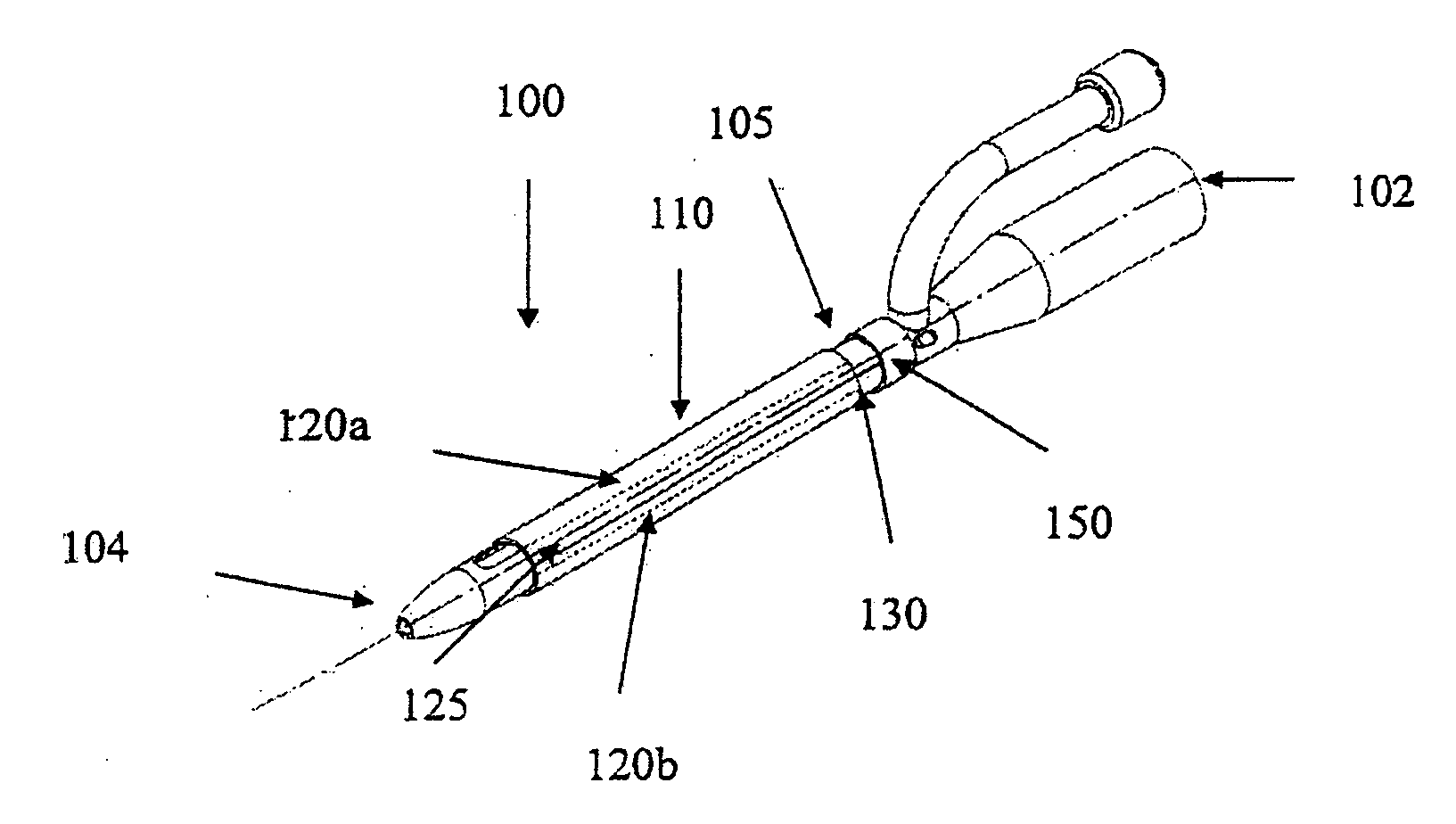
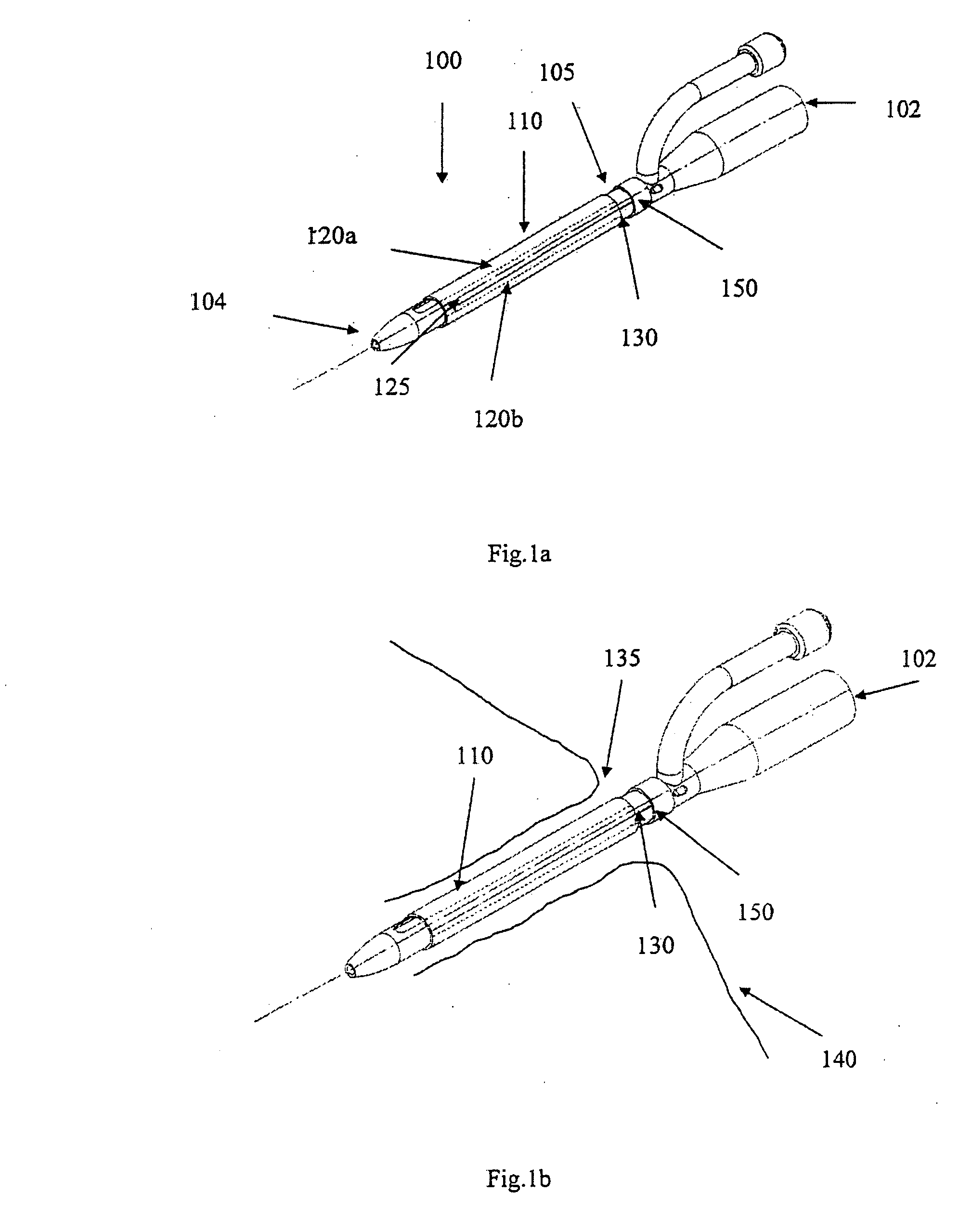
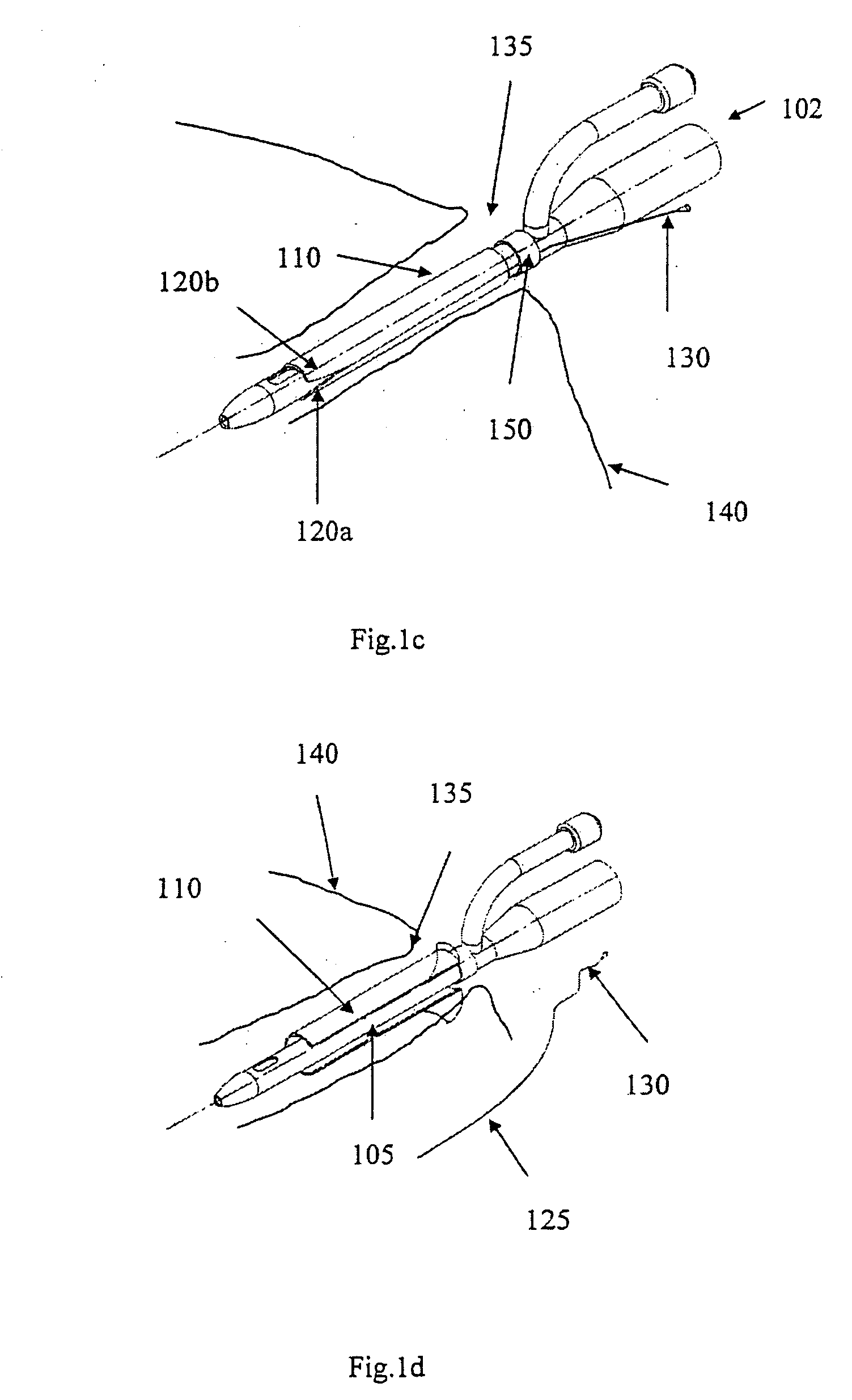
[0056]FIG. 1a shows an indwelling device 100 in accordance with a first embodiment of the invention. The device 100 has a proximal end 102, a distal end 104, and a cylindrical shaft 105 that may be solid or hollow. The shaft 105 is contained in an outer cover 110 having the general shape of a thin cylindrical shell. The outer cover 110 is formed from a biocompatible, elastic material, such as latex, that was stretched over the shaft 105, and allowed to contract on the shaft 105. The outer cover 110 is reversibly attached to the shaft 105 by circumferential elastic forces in the outer cover 110 that are exerted on the shaft 105. This prevents slipping of the outer cover 110 over the shaft 105 during insertion of the device 100 into the body, and maintains the outer cover 110 on the shaft 105 after insertion.

[0057] The outer cover 110 is formed from two materials. The first material is used to form the cover except in a narrow strip 125 that is formed from a second material. The two ...

second embodiment

[0070]FIG. 2a shows an indwelling device 200 in accordance with another embodiment of the invention. The device 200 has a proximal end 202, a distal end 204, and a cylindrical shaft 205 that may be solid or hollow. The shaft 205 is contained in an outer cover 210 having the general shape of a thin cylindrical shell. The outer cover 210 is formed from a biocompatible, elastic material, such as latex, that was stretched over the shaft 205, and allowed to contract on the shaft 205. The outer cover 210 is reversibly attached to the shaft 205 by circumferential elastic forces in the outer cover 210 that are exerted on the shaft 205. This prevents slipping of the outer cover 210 over the shaft 205 during insertion of the device 200 into the body, and maintains the outer cover 210 on the shaft 205 after insertion.

[0071] As shown in the insert FIG. 2a-I of FIG. 2a, the shaft has a longitudinal groove 215 that forms a track for a blade 220. The blade 220 is slidable along the groove 215. Du...

third embodiment

[0074]FIG. 3a shows a device 300 in accordance with another embodiment of the invention. The device 300 has a proximal end 302, a distal end 304, and a cylindrical shaft 305. The shaft 305 is contained in an outer cover 310 having the general shape of a thin cylindrical shell. The outer cover 310 is formed from a biocompatible, elastic material, such as latex. The outer cover 310 was formed from an inner cylindrical shell 322 and an outer cylindrical shell 324. The inner and outer shells 322 and 324 are welded together at a first circular seam 326 at its distal end and a second circular seam 327 at its proximal end. The outer cover 310 was stretched over the shaft 305, and allowed to constrict on the shaft 305. The outer cover 310 is reversibly attached to the shaft 305 by circumferential elastic forces in the outer cover 310 that are exerted on the shaft 305. This prevents movement of the outer cover 310 relative to the shaft 305 during insertion of the device 300 and maintains the...


PUM


Abstract

A medical device for insertion into a body having a surface covered by a detachable cover. The cover may be detached from the surface and removed from the body while the device is inserted in the body. The device may be, for example, a catheter, cannula, drain, stent, pacemaker, or electrode.

Description

FIELD OF THE INVENTION [0001] The present invention is in the field of medical devices, and more specifically relates to indwelling medical devices. BACKGROUND OF THE INVENTION [0002] There are many medical devices that are inserted into the body and left indwelling for a prolonged period of time. These include, for example, various types of catheters, cannulae, drains, implants, stents, pacemakers, electrodes and other devices. Some of these devices, such as a urinary catheter, when in use, extend from the exterior of the body into the body interior, passing through an orifice on the body surface. The orifice may be a natural orifice (e.g. mouth, meatus, nostrils, etc.) or an artificial orifice (e.g. a hole formed in the skin by a surgical incision). Other indwelling devices, such as a pacemaker or stent, are completely enclosed inside the body during use. Accessing these devices typically requires surgical incising or other invasive approaches. [0003] Although using indwelling dev...

Claims


Application Information

Patent Timeline
Patent Type & Authority Applications(United States)
IPC IPC(8): A61B19/00A61F2/86A61M25/00A61N1/05
CPCA61B19/38A61F2/86A61N1/056A61N1/05A61M25/0017A61B90/40
Inventor OSTFELD, ISHAYHIRSZOWICZ, ERAN
Owner OSTFELD ISHAY
Why Eureka
Try Eureka