Spin-printing of electronic and display components

a technology of electronic and display components and spin printing, which is applied in the direction of final product manufacturing, inks, solid-state devices, etc., can solve the problems of less than 100% additive process, system clogging, and inability to view fully additiv

Inactive Publication Date: 2005-04-28
EI DU PONT DE NEMOURS & CO
View PDF24 Cites 94 Cited by
  • Summary
  • Abstract
  • Description
  • Claims
  • Application Information

AI Technical Summary

Benefits of technology

[0042] g) and optionally heating the substrate and deposited fiber to a temperature sufficient to effect removal of the organic components.

Problems solved by technology

This system cannot be viewed as fully additive in that the portion of material diverted to the reservoir is lost, making the process less than 100% additive.
These systems are more prone to clogging when employing inks with high solids content, and it is a common feature that the first several drops on demand may not fire.
These applications do not anticipate the advantage of using a viscoelastic polymer solution having a low polymer content thereby maximizing the quantity of functional phase materials printed onto the substrate.
To achieve higher conductivities, the polymer fraction would have to be fired out, but the polymer content is so high that the volatilization process would destroy the lines.
Ultrafine particles often undergo aggregation and this makes it difficult to prepare any liquid dispersion in which the ultrafine particles are dispersed in a stable manner.
For this reason, when using such a liquid dispersion of ultrafine particles as ink for the inkjet printing, the ink suffers from a problem in that aggregates of the ultrafine particles present therein result in clogging of the ink jet nozzles.
However, the choice of a solvent suitably used in the ink for the ink jet printing has been quite difficult.
The properties required for an ink jet system are often at odds with the requirements for stable dispersions of the ultrafine particles.
It is difficult to build features to any appreciable thickness, though this can be done utilizing multiple passes.
Resolution is often compromised and it is difficult to obtain appreciable feature height to feature width because non-viscous, wetting fluids are employed.
The amount of drawing that can be done is limited, because above some maximum draw value the fibers tend to break.

Method used


Image

  • Spin-printing of electronic and display components
  • Spin-printing of electronic and display components
  • Spin-printing of electronic and display components

Examples


example 1

Demonstrating that the Technique Works with Non-Aqueous Systems

[0195] A solution of UHMW polydecene (estimated molecular weight greater than 2,000,000)(2.5 g) in hexane (50 mL) was prepared by cutting the sample of polydecene into small pieces and then placing the jar containing the polymer and solvent onto a roller mill (U.S. Stoneware Corp., Palestine Ohio) set on its lowest speed. Tumbling for 65 hours produced a viscoelastic, relatively homogeneous liquid or gel. The material could easily be drawn into long fibers.

[0196] A sample of Ferro silver (1.0 g, Ferro 7000 ultrafine silver powder, Ferro Corporation, Cleveland, Ohio) was dispersed in hexane (1 mL) in a 25 mL sample vial. A sample of polymer solution (1 mL) was added to the vial. Then an uncapped 1.5 mL vial was added to the sample vial. The capped sample vial was placed in a jar with padding and placed on the roller mill at its slowest speed for 24 hours. The small vial inside the sample vial served as a roller to dispe...

example 2

Demonstrating that the Technique Works with Conductive Materials in Aqueous Systems

[0199] A sample of UHMW polyethyleneoxide (2 g, Aldrich, Milwaukee, Wis. 18,947-2, molecular weight about 5,000,000) was dispersed quickly into highly stirred hot water 50 mL) in a jar. The jar containing the UHMW PEO and water was placed onto a roller mill (U.S. Stoneware Corp., Palestine OH) set on its lowest speed. Tumbling for 65 hours produced a viscous, relatively homogeneous liquid or gel. The material could easily be drawn into long fibers.

[0200] A sample of Ferro silver (1.0 g) was dispersed in water (1 mL) in a 25 mL sample vial. A sample of polymer solution (1 mL) was added to the vial. Then an uncapped 1.5 mL vial was added to the sample vial. The sample vial was placed in a jar with padding and placed on the roller mill at its slowest speed for 24 hours.

[0201] The sample was transferred to a 1 mL syringes having a needle that had been cut off to a flat tip. Small samples were forced fr...

example 3

Demonstrating that the Technique Works with Complex Additives and Adjuvants

[0203] A sample (10 g) of fully formulated DuPont Fodel® (DC-204) photocurable silver conductor paste (60% silver by weight) was obtained from DuPont Micro Circuit Materials, Wilmington, Del. The major constituents by weight were silver (60%), trimethylpentanediol monoisobutyrate (10%), acrylic resin (6%), modified acrylate ester (3%), glass frit (3%), and other smaller components including isopropanol, diethylthioxanthone, ethyl 4-dimethylaminobenzoate, methyl methacrylate, methacrylic acid, and 2,2-dimethoxy-2-phenylacetophenone. The glass frit is composed of the component weight % of the following: SiO2 (9.1), Al2O3 (1.4), PbO (77.0), B2O3 (12.5). The sample was combined with poly(ethylene oxide) (Aldrich, Milwaukee, Wis. 18,947-2, molecular weight about 5,000,000), and methanol (0.6 g). The slurry was placed in a 25 mL vial and placed on a roller mill (U.S. Stoneware Corp., Palestine Ohio) at slowest spe...


PUM

PropertyMeasurementUnit
weight fractionaaaaaaaaaa

Abstract

The present invention is directed to a process for printing conductors, insulators, dielectrics, phosphors, emitters, and other elements that may be for electronics and display applications. The present invention also relates to viscoelastic compositions used in this printing process. The present invention further includes devices made therefrom.

Description

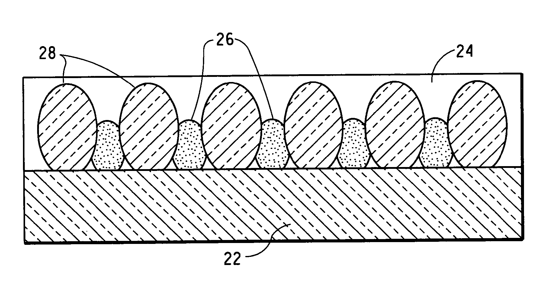
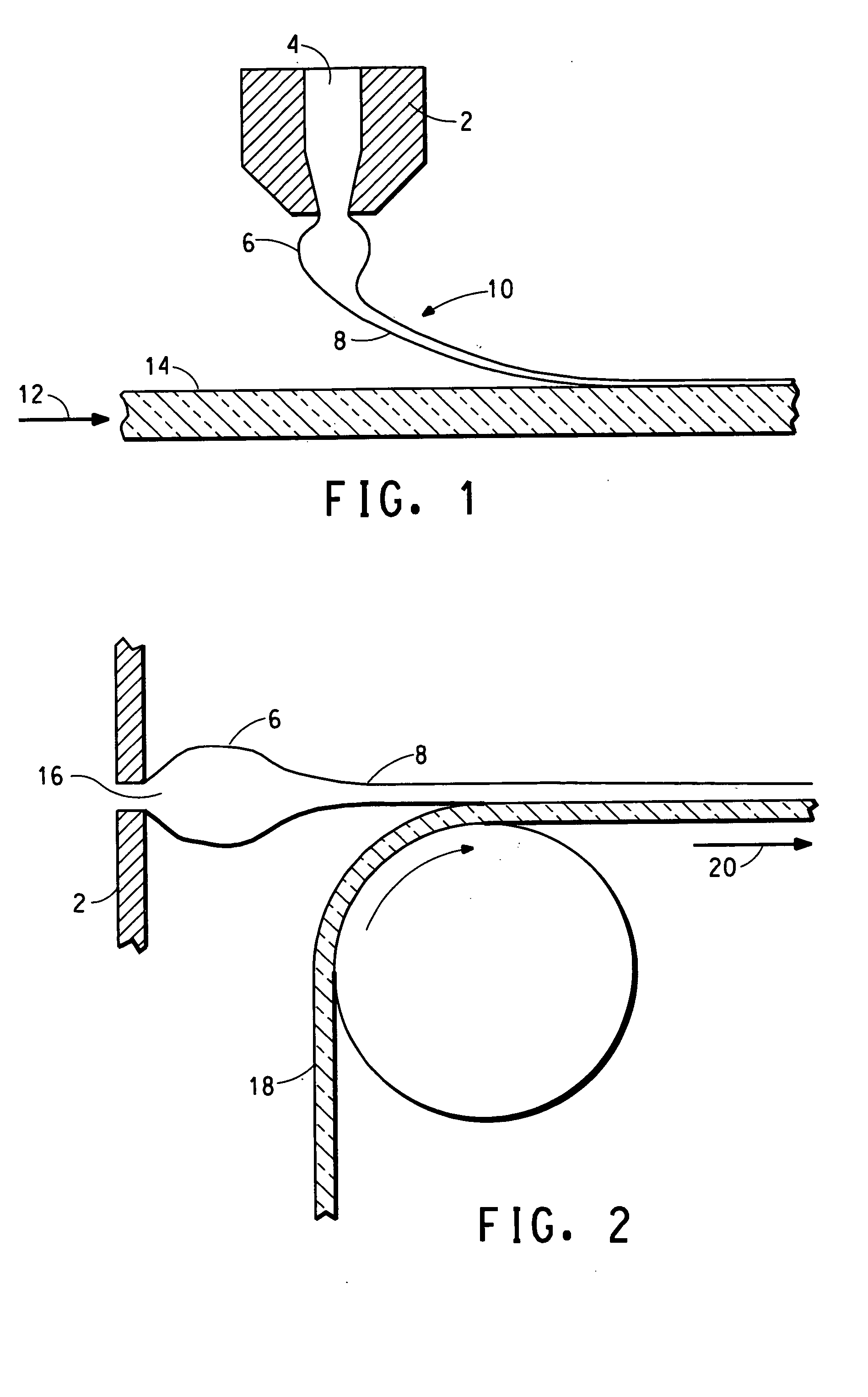
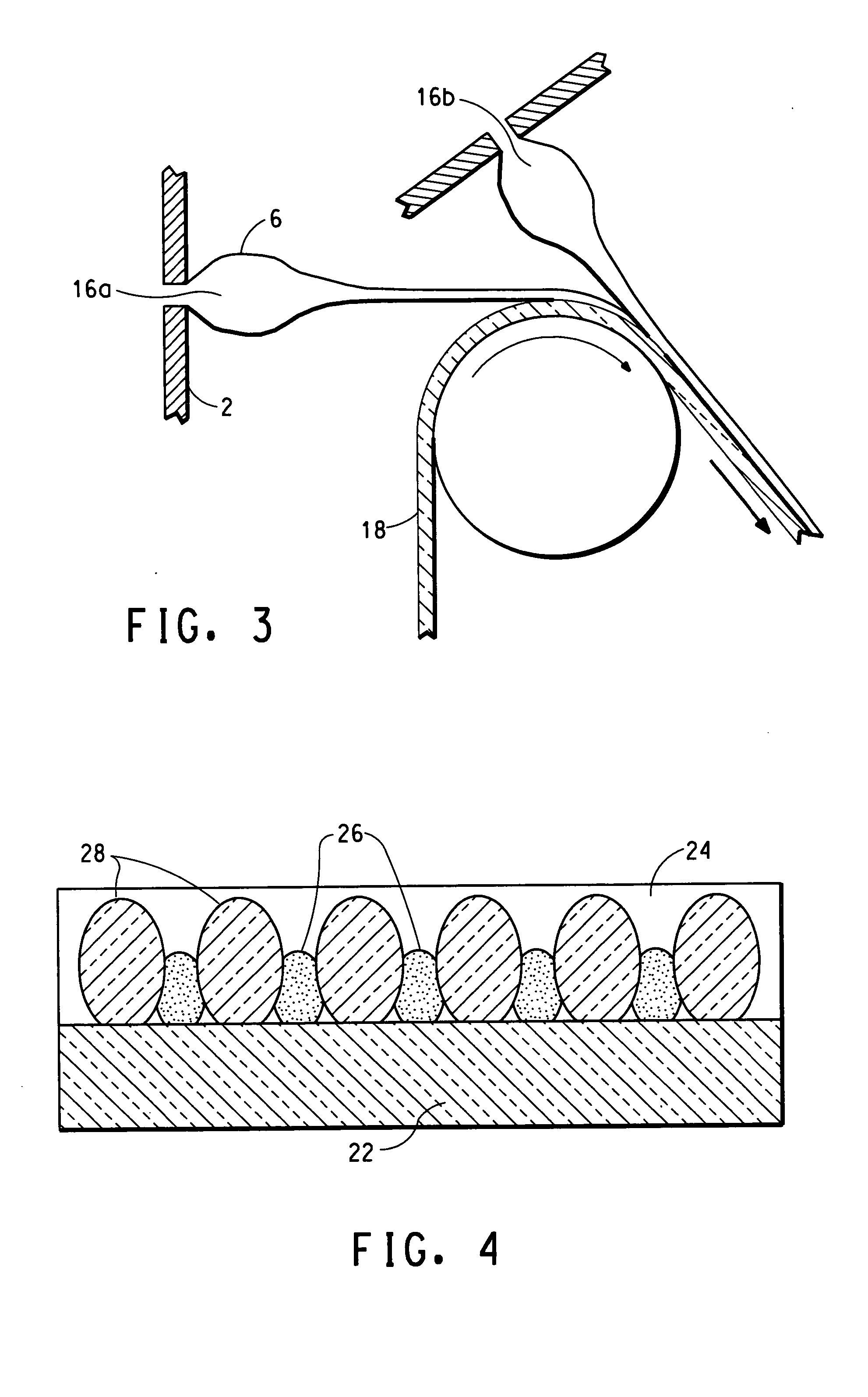
FIELD OF THE INVENTION [0001] The present invention is directed to a process for spin printing conductors, insulators, dielectrics, phosphors, emitters, and other elements that may be used for electronics and display applications. The present invention also relates to compositions used in this printing process. The present invention further includes devices made therefrom. TECHNICAL BACKGROUND [0002] The electronics, display and energy industries rely on the formation of coatings and patterns of conductive and other electronically active materials to form circuits on organic and inorganic substrates. The primary methods for generating these patterns are screen printing for features larger than about 100 μm and thin film and etching methods for features smaller than about 100 μm. Other subtractive methods to attain fine feature sizes include the use of photo-patternable pastes and laser trimming. [0003] It is the trend in the electronics industry to make smaller and less expensive el...

Claims


Application Information

Patent Timeline
Patent Type & Authority Applications(United States)
IPC IPC(8): C08F2/00C08K3/00G03F7/00G03F7/004H05K3/12
CPCC08F10/10Y10T428/25D01D10/02D01F1/09D01F1/10D01F8/04G03F7/0047H01G9/2031H01L51/0022H05K1/092H05K1/097H05K3/1241H05K2201/0314H05K2203/0126Y02E10/542C09D11/52Y10T428/256Y02E10/549C08F2500/01Y02P70/50H10K71/611C08K3/00G03F7/00B32B5/16
Inventor ITTEL, STEVEN DALECRAWFORD, JEFFREY
Owner EI DU PONT DE NEMOURS & CO
Why Eureka
Try Eureka