
Cooling technique

Inactive Publication Date: 2005-05-05
CANON KK
View PDF19 Cites 31 Cited by
  • Summary
  • Abstract
  • Description
  • Claims
  • Application Information

AI Technical Summary

Benefits of technology

[0008] It is accordingly an object of the present invention to provide a cooling technique by which at least one of the inconveniences described above can be solved.
[0014] In Accordance with the present invention, the necessity of applying an electric current in the vicinity of a subject of cooling as in the case using a Peltier device is removed, and also adverse influence on anything other than the subject of cooling, from cooling pipes, can be reduced.

Problems solved by technology

With the cooling based on radiation, if the temperature difference between the subject of cooling and the radiation plate is not large, a desired cooling rate is not obtainable.
Furthermore, while the foregoing example uses Peltier devices, in some cases it is difficult to use such Peltier device.
Therefore, if it is incorporated into an EB (electron beam) exposure apparatus, the exposure precision may be adversely affected thereby.
In such case, Peltier devices can not be used.
This causes thermal deformation and degradation of the positioning precision.

Method used


Image

  • Cooling technique
  • Cooling technique
  • Cooling technique

Examples


first embodiment

[First Embodiment]

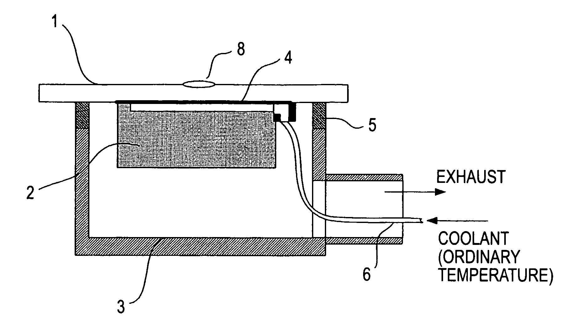
[0026]FIG. 1 shows a cooling mechanism according to a first embodiment of the present invention. FIG. 1 illustrates the structure for controlling a radiation plate temperature on the basis of heat of vaporization of water. Water which is temperature controlled to about the same temperature of the structure 110 and 211 (FIG. 5) which constitutes a positioning device, that is, usually about 23° C., is supplied to a porous material member 2 through a flowpassage 6. The porous material member 2 is disposed inside a container 3 which is vacuum exhausted by means of a vacuum pump, for example. The water supplied therein is dispersed within the porous material member 2 and, when a vapor pressure (or steam pressure) or lower pressure is reached, vaporization occurs. For example, the vapor pressure of water at 0° C. is 610 Pa and, therefore, by keeping the inside pressure of the container 3 at about 100 Pa, the water can be well vaporized even if the temperature of the poro...

second embodiment

[Second Embodiment]

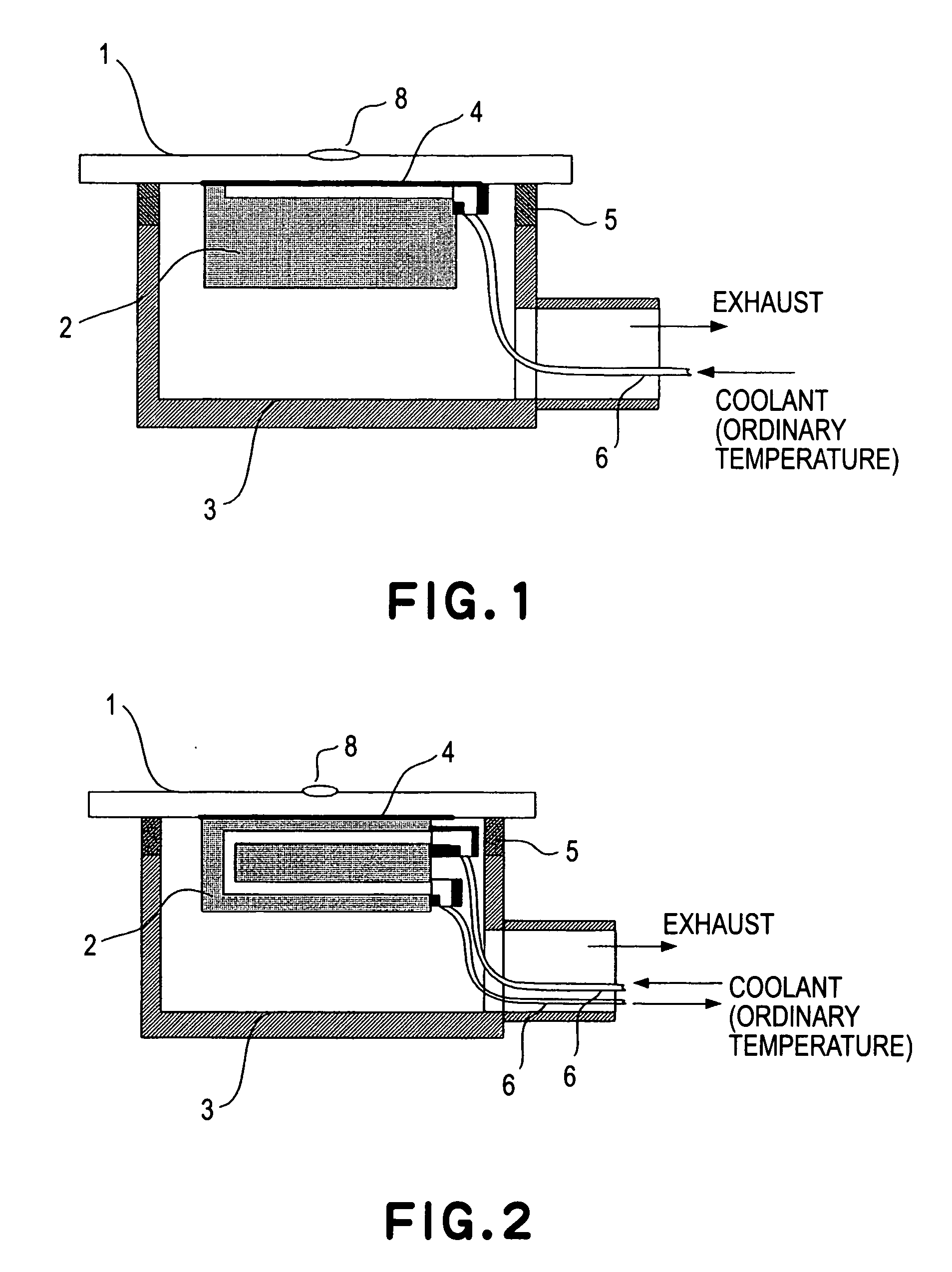
[0033]FIG. 2 shows a second embodiment of the present invention. This embodiment differs from the first embodiment in that water (coolant) is circulated through a porous material member 2 and that a portion of the circulated water is vaporized through the porous material member 2. Usually, a positioning device may be equipped with circulation of water for cooling. Thus, a portion of such circulation water may be bypassed toward the porous material member 2. In that occasion, there are advantages that the liquid pressure control is easy, and that the liquid is not easily solidified within the flowpassage 6 even if the set radiation plate temperature is low.

third embodiment

[Third Embodiment]

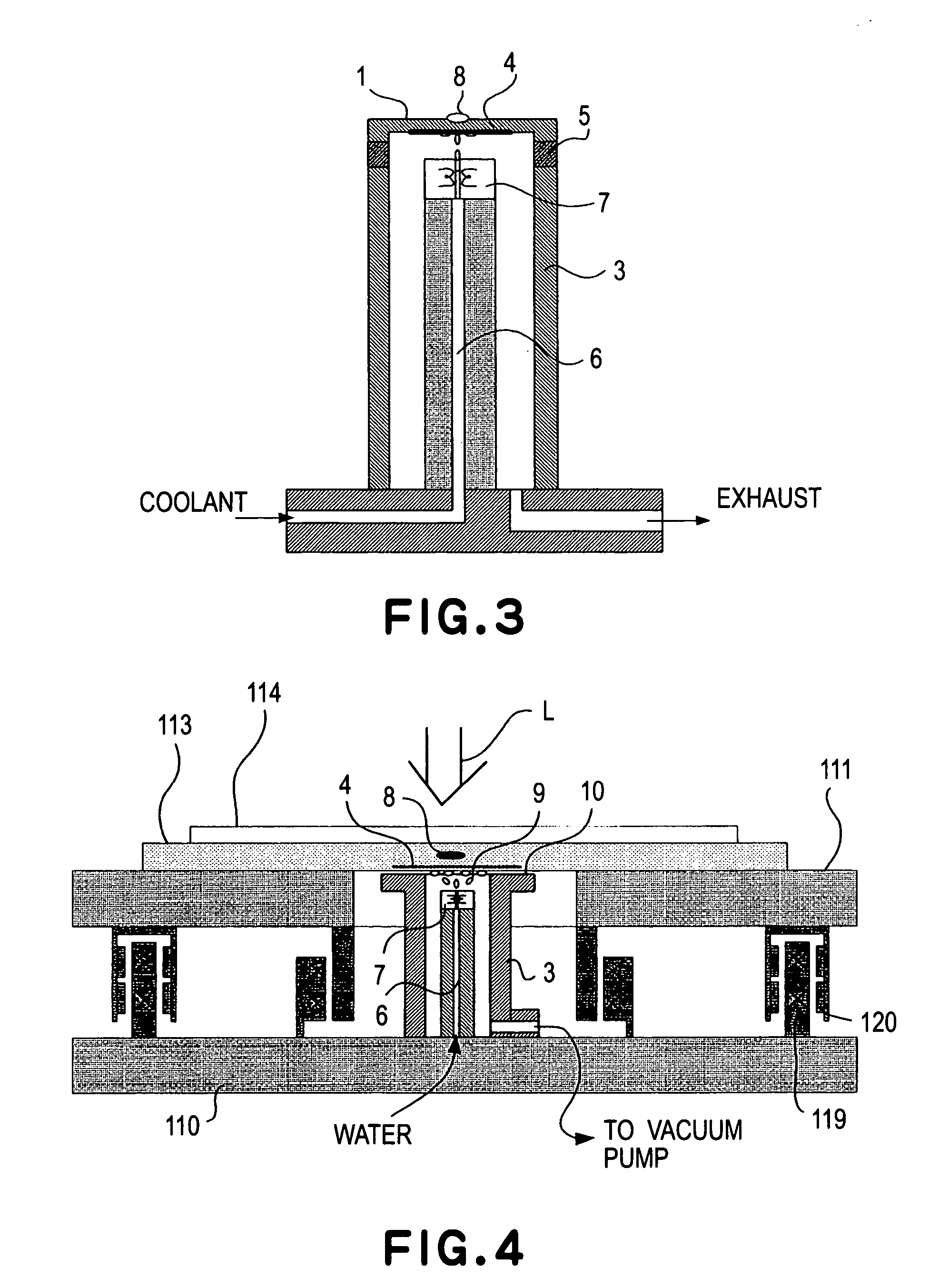
[0034]FIG. 3 shows a third embodiment of the present invention. In the cooling mechanism of FIG. 3, a liquid is directly applied against the back of a radiation plate. More specifically, water being supplied through a flowpassage 6 is applied (or discharged) from a nozzle 7 directly against the back of a radiation plate 1. Since the inside pressure of a vacuum container 3 is held by means of a vacuum pump (not shown), for example, at a pressure sufficiently smaller than the steam pressure of the water, the discharged water is vaporized while depriving, from the radiation plate, a heat quantity corresponding to the vaporization heat. With this arrangement, the radiation plate 1 can be cooled, and the temperature thereof can be reduced to about 0° C. As described with reference to the first embodiment, the temperature control for the radiation plate may be carried out by controlling energization of a heater 4 provided adjacent the radiation plate (at the back of the ...


PUM


Abstract

Disclosed is a positioning apparatus, including a positioning unit, and a temperature adjusting unit which adjusts a temperature of at least a portion of the positioning unit, the temperature adjusting unit including a cooling mechanism based on vaporization heat of a liquid Also disclosed is a cooling apparatus, including a container, a supplying unit which supplies a liquid to the container, and an exhaust unit which exhausts the container.

Description

FIELD OF THE INVENTION AND RELATED ART [0001] This invention relates to a cooling technique suitably usable to an exposure apparatus for manufacture of devices such as semiconductor devices having a fine pattern, or to precision measuring devices, for example. [0002] Referring to FIGS. 5 and 6, a structure of a positing device such as disclosed in Japanese Laid-Open Patent Application, Publication No. 2003-58258 will be explained. FIG. 5 illustrates a positioning device disposed in a vacuum ambience, for performing high-precision positioning, as well as a cooling mechanism therefor. FIG. 6 shows details of the cooling mechanism. [0003] In FIG. 5, a substrate 114 such as a semiconductor wafer is placed on a chuck 113 which is supported by a top plate 111. The top plate 111 is floated by non-contact self-weight compensating mechanism (not shown) whose spring characteristic can be almost disregarded. Also, the top plate 111 is positioned without contact, by means of a linear motor (119...

Claims


Application Information

Patent Timeline
IPC IPC(8): F25D7/00G03F7/20H01J37/20G03F9/00H01J37/305H01L21/027
CPCG03F7/70875G03F7/70691
Inventor EMOTO, KEIJI
Owner CANON KK
Learn More