Electrical contact, method of manufacturing the same, electrode for vacuum interrupter, and vaccum circuit breaker

a manufacturing method and technology of electrical contacts, applied in the direction of contact materials, air breakers, contact materials, etc., can solve the problem of not revealing the concentration of impurities, and achieve the effect of eliminating post-machining, shortening the mold life, and reducing the productivity of contacts

Inactive Publication Date: 2005-05-05
JAPAN AE POWER SYST
View PDF2 Cites 7 Cited by
  • Summary
  • Abstract
  • Description
  • Claims
  • Application Information

AI Technical Summary

Benefits of technology

[0023] In the sintering method of the present invention, the mixed powder is molded into a propeller shape having the center aperture in the center thereof, where the molded is divided by slits. The pressure of the molding is 120 to 500 MPa to obtain a density of 65 to 75%. If the pressure is less than that, the molding may crumble; if the density is more than that, the molding may tend to stick to the mold thereby to shorten the life of the mold and lower the productivity of the contacts.
[0024] The sintering atmosphere is preferably an Ar atmosphere of 20 to 60 Pa. The sintering temperature is lower than the melting point of Cu. when the sintering is carried out under the gaseous atmosphere pressure of 20 to 60 Pa, surface oxide film on Cu is removed and evaporation of Cu is prevented thereby to produce a dense electric contact. The sintering temperature is lower than the melting point of Cu, preferably 1050 to 1070° C., so that electrical contact with a precise contour is obtained to eliminate post-machining and to lower the production coat. The electrode for a vacuum interrupter comprises the above-mentioned disc as the electrical contact and an electrode rod connected to the disc.

Problems solved by technology

However, the publication does not disclose the concentrations of impurities.

Method used


Image

  • Electrical contact, method of manufacturing the same, electrode for vacuum interrupter, and vaccum circuit breaker
  • Electrical contact, method of manufacturing the same, electrode for vacuum interrupter, and vaccum circuit breaker
  • Electrical contact, method of manufacturing the same, electrode for vacuum interrupter, and vaccum circuit breaker

Examples


example 1

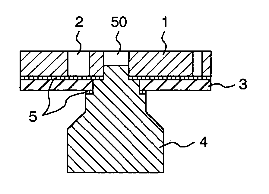
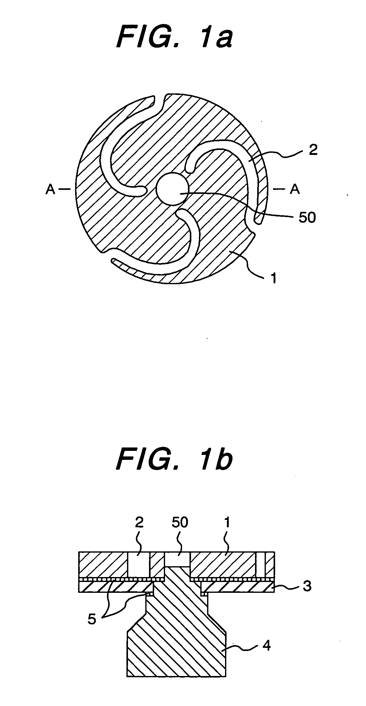
[0029]FIG. 1 shows a cross sectional view of an electrode for a vacuum interrupter of the present invention. (a) is a plan view of the electrical contact and (b) is a cross sectional view along the A-A line of (a). As shown in FIG. 1, the electrical contact 1 is made of a disc member of a propeller shape that has spiral grooves 2 for preventing stagnation of arc by giving driving force to the arc and a center aperture 50. The electrode for the vacuum interrupter comprises the electrical contact 1, a non-magnetic reinforcement member 3 made of stainless steel, the electrode rod 4, and a solder material 5. The reinforcement member 3 is disposed if necessary; if the strength of the electrical contact is enough, the reinforcement member can be omitted.

[0030] The method of manufacturing the electrical contact is as follows. Thermit Cr powder and electrolyzed chromium powder having a particle size of not larger than 63 μm and electrolyzed copper powder having a particle size of not large...

example 2

[0040] In this example, interruption tests of the electrodes prepared in the example 1 for the vacuum interrupter were conducted to evaluate interruption performance. The interruption tests were carried out by installing the electrodes prepared in Example 2 to a vacuum interrupter of a rated voltage of 12 kV, a rated current of 600 A, and a rated interruption current of 25 kA, and assembled in the vacuum circuit breaker shown in Example 3. Table 1 shows the results of interruption tests. In Nos. 1 to 11, Thermit Cr powder was used, and in Nos. 12-13, electrolyzed Cr powder was used.

TABLE 1CompositionImpuritiesPerformance% by weight(ppm)(relative value)No.CrCuTeOAlSiABC11585—557981341.050.900.9522080—70214914211132079.950.0574815113610.971.1042079.50.586913117710.951.4052575—7551681790.971.101.0563070—8372202250.951.181.1271090—451279660.950.800.7884060—10023083430.901.251.1592079.970.0371913712910.971102079.30.039071531840.950.851.551120790.711161441800.900.801.60122079.951.022371...


PUM

PropertyMeasurementUnit
particle sizeaaaaaaaaaa
molding pressureaaaaaaaaaa

Abstract

The present invention relates to an sintered electric contact containing Cr in an amount of 15 to 30% by weight and Cu being balance as main components, 0.05 to 0.5% by weight of Te, 100 to 3000 ppm of O, 7.5 to 900 ppm of Al, and 15 to 750 ppm of Si.

Description

CLAIM OF PRIORITY [0001] The present application claims priority from Japanese application serial No. 2003-371369, filed on Oct. 31, 2003, the content of which is hereby incorporated by reference into this application. TECHNICAL FIELD [0002] The present invention relates to a new electrical contact, a method of manufacturing the contact, an electrode for a vacuum interrupter, and a vacuum circuit breaker. BACKGROUND OF THE INVENTION [0003] As an electrode for a vacuum interrupter disposed in a vacuum circuit breaker, there is disclosed in Patent publication No. 1 and Patent Publication No. 2 a sintered Cr—Cu composite alloy that is manufactured by pressure-molding mixed powder of Cr as a refractory metal and Cu as a high electrical conductivity metal, followed by sintering the mixed powder at a temperature lower than a melting point of Cu. Further, in Patent Publication No. 3, there is disclosed an electrode material that is manufactured by pressure-molding a mixed powder of Cr powd...

Claims


Application Information

Patent Timeline
Patent Type & Authority Applications(United States)
IPC IPC(8): B22F1/00C22F1/00B22F3/10C22C9/00C22F1/08H01H1/02H01H1/025H01H1/06H01H11/04H01H33/66
CPCH01H1/0206H01H33/664H01H11/048
Inventor KIKUCHI, SHIGERUBABA, NOBORUNISHIJIMA, AKIRAFUKAI, TOSHIMASA
Owner JAPAN AE POWER SYST
Why Eureka
Try Eureka