High performance ion mobility spectrometry using hourglass electrodynamic funnel and internal ion funnel

a technology of ion mobility and funnel, which is applied in the direction of particle separator tube details, instruments, separation processes, etc., can solve the problems of ims/ms systems not reaching their full potential as analytical instruments, and the limitations of techniques, so as to increase the sensitivity of ion mobility spectrometry/mass and reduce the loss of ions

Active Publication Date: 2005-05-05
BATTELLE MEMORIAL INST
View PDF1 Cites 42 Cited by
  • Summary
  • Abstract
  • Description
  • Claims
  • Application Information

AI Technical Summary

Benefits of technology

[0007] Accordingly, it is an object of the present invention to provide methods and apparatus that enable increased sensitivity in ion mobility spectrometry / mass spectrometry instruments and substantially reduce the loss of ions in ion mobility spectrometer drift tubes. These and other objects of the present invention are accomplished by providing a method and apparatus for analyzing ions utilizing an hourglass electrodynamic ion funnel at the entrance to the drift tube and / or an ion funnel at the exit of the drift tube, as shown in the cutaway schematic drawing of FIG. 1. Briefly, the present invention comprises an hourglass electrodynamic funnel 1 formed of at least an entry element 2, a center element 3, and an exit element 4, each of said elements having an aperture. The entry element 2 is aligned such that a passageway for charged particles is formed through the aperture within the entry element 2, through an aperture in the center element 3, and then through the aperture in the exit element 4. It is important that the aperture in the center element 3 is smaller than the aperture of the entry element 2 and the aperture of the exit element 4. Typically, the hourglass electrodynamic funnel 1 will consist of more than three elements, perhaps as many as several hundred elements. It is not necessary that the center element 3 be at the exact middle of all elements. In an embodiment, for example, with 100 elements, the center element 3 could be the 80th element, rendering the electrodynamic funnel asymmetric. All that is required of the center element 3 is that it be the smallest of the elements, and that the center element 3 have at least one element (the entry 2 and exit element 4) to each of both sides. Conceptually, therefore, three elements are the minimum necessary to describe and operate the invention.

Problems solved by technology

While the general concept of such systems has thus long been recognized, those having skill in the art have also recognized limitations associated with the technique when put into practice.
Despite these and other improvements, problems associated with loss of ions in ion mobility spectrometer (IMS) drift tubes have continued to prevent IMS / MS systems from reaching their full potential as analytical instruments.

Method used


Image

  • High performance ion mobility spectrometry using hourglass electrodynamic funnel and internal ion funnel
  • High performance ion mobility spectrometry using hourglass electrodynamic funnel and internal ion funnel
  • High performance ion mobility spectrometry using hourglass electrodynamic funnel and internal ion funnel

Examples


Embodiment Construction

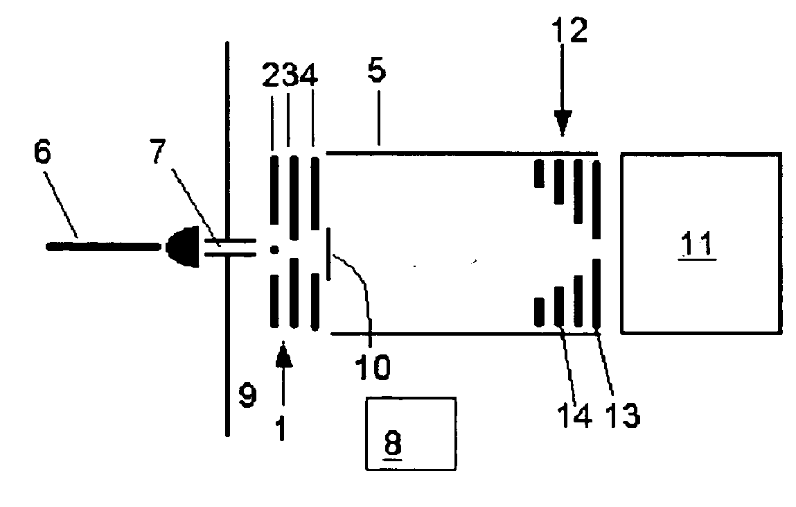
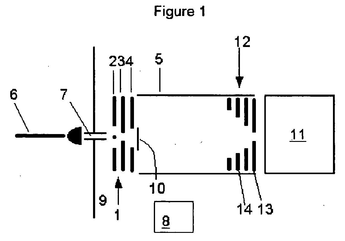
[0028] A device was constructed to demonstrate the advantages and application of the present invention consisting of three sections: an ion source, and ion mobility spectrometer (IMS) drift tube for spatial ion separation, and a mass spectrometer for mass analysis of separated ion packets. Except as noted below, the device utilized the general arrangement of each of these components as shown in the conceptual drawing shown in FIG. 1. While all voltages listed below are for positively charged ions (cations), those having skill in the art will readily recognize that the polarities can readily be inverted to analyze negatively charged ions (anions).

[0029] This ion source section comprises an electrospray ionization (ESI) source that generates solvated ions, a heated capillary that desolvates them, and an hourglass electrodynamic (ED) ion funnel that further desolvates and focuses them into IMS. The ESI and the heated capillary were standard instruments available commercially from Wate...


PUM

PropertyMeasurementUnit
lengthaaaaaaaaaa
internal diameteraaaaaaaaaa
voltagesaaaaaaaaaa

Abstract

A method and apparatus enabling increased sensitivity in ion mobility spectrometry/mass spectrometry instruments which substantially reduces or eliminates the loss of ions in ion mobility spectrometer drift tubes utilizing a device for transmitting ions from an ion source which allows the transmission of ions without significant delay to an hourglass electrodynamic ion funnel at the entrance to the drift tube and/or an internal ion funnel at the exit of the drift tube. An hourglass electrodynamic funnel is formed of at least an entry element, a center element, and an exit element, wherein the aperture of the center element is smaller than the aperture of the entry element and the aperture of the exit elements. Ions generated in a relatively high pressure region by an ion source at the exterior of the hourglass electrodynamic funnel are transmitted to a relatively low pressure region at the entrance of the hourglass funnel through a conductance limiting orifice. Alternating and direct electrical potentials are applied to the elements of the hourglass electrodynamic funnel thereby drawing ions into and through the hourglass electrodynamic funnel thereby introducing relatively large quantities of ions into the drift tube while maintaining the gas pressure and composition at the interior of the drift tube as distinct from those at the entrance of the electrodynamic funnel and allowing a positive gas pressure to be maintained within the drift tube, if desired. An internal ion funnel is provided within the drift tube and is positioned at the exit of said drift tube. The advantage of the internal ion funnel is that ions that are dispersed away from the exit aperture within the drift tube, such as those that are typically lost in conventional drift tubes to any subsequent analysis or measurement, are instead directed through the exit of the drift tube, vastly increasing the amount of ions exiting the drift tube.

Description

[0001] This application is a Continuation-In-Part of U.S. application Ser. No. 10 / 699,006 filed Oct. 30, 2003, now U.S. Pat. No. ______.[0002] This invention was made with Government support under Contract DE-AC0676RLO1830 awarded by the U.S. Department of Energy. The Government has certain rights in the invention.BACKGROUND OF THE INVENTION [0003] The hope of achieving high performance identification of ionic species using ion mobility drift tubes coupled with time of flight mass spectrometers has long been held by those skilled in the art. The general concept has been known since at least the publication of the paper entitled “Ion Mobility / Mass Spectrometric Investigation of Electrospray Ions” by R. Guevremont, K. W. M. Siu, and L. Ding in the Proceedings of the 44th ASMS Conference, p. 1090 (1996). This paper, and all other papers and patents identified herein are hereby explicitly incorporated into this disclosure by this reference. The concept was again published in the paper “...

Claims


Application Information

Patent Timeline
Patent Type & Authority Applications(United States)
IPC IPC(8): G01N27/64H01J49/02H01J49/04H01J49/06H01J49/16H01J49/40H01J49/42
CPCG01N27/622H01J49/40H01J49/066
Inventor SMITH, RICHARD D.TANG, KEQISHVARTSBURG, ALEXANDRE A.
Owner BATTELLE MEMORIAL INST
Why Eureka
Try Eureka