Laser engraving methods and compositions, and articles having laser engraving thereon

a laser engraving and composition technology, applied in the direction of photosensitive material auxillary/base layer, thermography, nuclear engineering, etc., can solve the problems of counterfeiting or alteration, laser marking of some types of materials does not produce an adequate contrast for all applications, and certain limitations still exist, so as to reduce the cost of consumables, the effect of easy counterfeiting or alteration

Active Publication Date: 2005-05-05
L 1 SECURE CREDENTIALING
View PDF99 Cites 77 Cited by
  • Summary
  • Abstract
  • Description
  • Claims
  • Application Information

AI Technical Summary

Benefits of technology

[0025] Using laser beams to write or engrave information to ID cards presents a number of advantages over conventional printing. For example, the foaming of the thermoplastic that can occur with some types of laser engraving can be adapted to provide an indicium having a tactile feel, which is a useful authenticator of a data carrier that also can be very difficult to counterfeit or alter. In addition, laser engraving generally does not require the use of ink, which can reduce the cost of consumables used to manufacture an ID card. Laser engraving can also be more durable than ink printing, and more resistant to abrasion (which can be particularly useful if a counterfeiter attempts to “rub off” an indicium on an ID card). The resolution and print quality of laser engraving often can be higher than that of conventional ink-based printing. Laser engraving also can be a more environmentally friendly manufacturing process than printing with ink, especially because solvents and other chemicals often used with ink generally are not used with laser engraving.

Problems solved by technology

Despite the advantages of laser engraving, certain limitations still exist.
Even when using known laser-enhancing additives, laser marking of some types of materials does not produce an adequate contrast for all applications.
Some types of materials, such as silica filled polyolefin, TESLIN core ID documents and TESLIN composite structures (TESLIN is available from PPG Industries, Inc., Pittsburgh, Pa.) using conventional over-laminate materials, are not easily laser engraved.
Further, even with use of known laser additives, laser engraving can take too much time and / or too much laser energy to be useful in some manufacturing environments.

Method used


Image

  • Laser engraving methods and compositions, and articles having laser engraving thereon
  • Laser engraving methods and compositions, and articles having laser engraving thereon
  • Laser engraving methods and compositions, and articles having laser engraving thereon

Examples


second embodiment

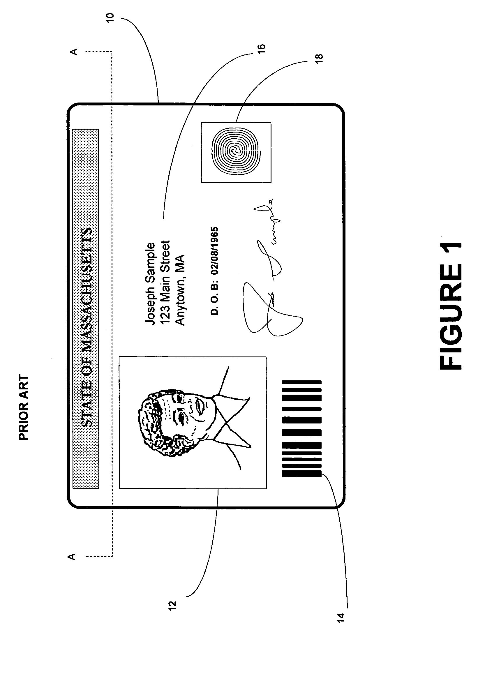
[0114] For example, FIG. 4 is an illustrative cross sectional view of an identification document in accordance with the first aspect of the invention. In the embodiment of FIG. 4, the ID document 10 preferably includes a multi-layered structure. For purposes of illustration, however, the ID document 10 may have an front outward appearance generally similar to the identification document 10 of FIG. 1, although the construction and components of the cross-section shown in FIG. 4 differs from the prior art. In the embodiment of FIG. 4, the portion of first laminate 52 containing the inventive laser enhancing additive is disposed at least partially within a layer of another material, such as so-called “plain” laminate 56 (i.e., laminate that does not contain the inventive laser enhancing additive). When a laser beam is applied to the first laminate 52, a third indicium 54G is formed. The plain laminate 56 may comprise a material that is inherently sensitive to laser radiation or can be ...

third embodiment

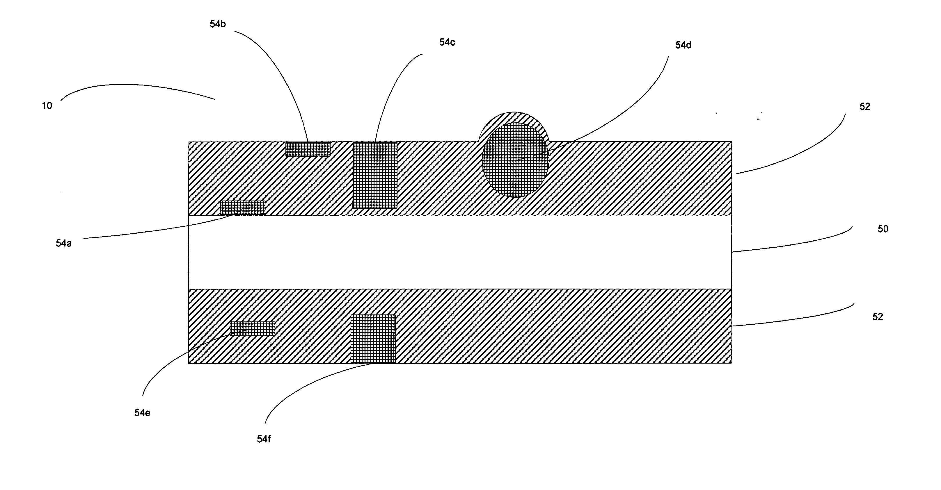
[0115]FIG. 5 is an illustrative cross sectional view of an identification document 10 in accordance with the first aspect invention. In the embodiment of FIG. 5, the ID document 10 preferably includes a multi-layered structure. For purposes of illustration, however, the ID document 10 may have an front outward appearance generally similar to the identification document 10 of FIG. 1, although the construction and components of the cross-section shown in FIG. 5 differs from the prior art. In the embodiment of FIG. 5, a first portion of the inventive laser enhancing additive is disposed in a first laminate layer 52 and a second portion of the inventive laser enhancing additive is disposed in a second laminate layer 55. Specifically, in this embodiment, the first laminate layer 52 contains an effective amount of at least one of copper potassium iodide (CuKI3) or copper iodide (CuI) and the second laminate layer 55 contains an effective amount of at least one of the following: zinc sulfi...

fourth embodiment

[0122] The inventive laser enhancing additive also can be used in a laminate that has one or more additional laminate layers bonded over it. For example, FIG. 6 is an illustrative cross sectional view of an identification document in accordance with the invention. In the embodiment of FIG. 6, the ID document 10 preferably includes a multi-layered structure. For purposes of illustration, however, the ID document 10 may have an front outward appearance generally similar to the identification document 10 of FIG. 1, although the construction and components of the cross-section shown in FIG. 6 differs from the prior art. In FIG. 6, the ID card 10 includes a core material 50 (shown for illustrative purposes only to be about 10 mils thick) to which is laminated a layer (shown for illustrative purposes only to be about 5 mils thick) of first laminate 52 to which the inventive laser enhancing additive is added. Over the first laminate 52 is a layer of second laminate 58 (shown for illustrati...


PUM

PropertyMeasurementUnit
thickaaaaaaaaaa
thickaaaaaaaaaa
thicknessaaaaaaaaaa

Abstract

The invention provides a composition having laser engraving properties, comprising a host material and an effective amount of a laser enhancing additive. The laser enhancing additive comprises a first quantity of least one of copper potassium iodide (CuKI3) or Copper Iodide (CuI), and a second quantity at least one substance selected from the group consisting of zinc sulfide (ZnS), barium sulfide (BaS), alkyl sulfonate, and thioester. The composition can be engraved with grayscale images by an Nd:Yag laser and can be added to laminates or coatings. The composition can be used during the manufacture of many articles of manufacture, including identification documents.

Description

RELATED APPLICATION DATA [0001] The present application is a continuation of U.S. patent application Ser. No. 10 / 326,886, filed Dec. 20, 2002 (Publication No. 2003-0234286), which claims priority to the following United States Provisional Applications: [0002] Sensitizing Materials for Laser Engraving (Application No. 60 / 344,677; Attorney Docket No. PO503—Inventor Brian Labrec), filed Dec. 24, 2001; [0003] Laser Engraving Coating System (Application No. 60 / 344,675; Attorney Docket No. PO515—Inventor Brian Labrec), filed Dec. 24, 2001; and [0004] Forming Variable Information In Identification Documents By Laser Ablation (Application No. 60 / 344,676, Attorney Docket No. PO516—Inventor: Brian LaBrec). [0005] The above listed applications are incorporated herein by reference in their entirety. [0006] U.S. patent application Ser. No. 10 / 326,886 is related to U.S. patent application Ser. No. 09 / 747,735, filed Dec. 22, 2000, Ser. No. 09 / 602,313, filed Jun. 23, 2000, and Ser. No. 10 / 094,593, ...

Claims


Application Information

Patent Timeline
Patent Type & Authority Applications(United States)
IPC IPC(8): B23K26/00B32B9/04B41CB41M3/14B41M5/24B41M5/26B42D15/10C08K3/16C08K3/30G03C1/00G03C1/492G03C1/494G03C1/76G06K5/00G06K19/02H01C13/00
CPCB41M3/14B41M5/24B41M5/267B41M7/0027Y10T428/24479C08K3/30Y10S430/146B42D25/41Y10T428/24802C08K3/16
Inventor LABREC, BRIAN C.JONES, ROBERT L.
Owner L 1 SECURE CREDENTIALING
Why Eureka
Try Eureka