Freeze tolerant fuel cell power plant with a two-component mixed coolant

a fuel cell and mixed coolant technology, applied in the direction of fuel cells, solid electrolyte fuel cells, cell components, etc., can solve the problems of mechanical damage, complex and costly plant systems, and difficulty in water management, and achieve the effect of improving the mixing of coolant flowing

Inactive Publication Date: 2005-05-05
INT FUEL CELLS
View PDF5 Cites 10 Cited by
  • Summary
  • Abstract
  • Description
  • Claims
  • Application Information

AI Technical Summary

Benefits of technology

[0009] The freeze tolerant fuel cell power plant of the invention may also include a two-component mixing system. The mixing system includes a coolant diversion valve for selectively directing none, all or a portion of the two-component mixed coolant from the coolant loop to the accumulator; a water immiscible fluid feed valve that selectively directs the flow of the water immiscible fluid from the accumulator into the coolant loop; a suction generating eductor to apply a suction force to the accumulator for withdrawing the water component of the two-component fluid from the accumulator into the coolant loop, and a mixer for mixing the water component from the accumulator with the water immiscible fluid within the coolant loop. The mixing system serves to enhance mixing of the two-component mixed fluid that provides water management and cooling functions during a steady-state operation of the plant.
[0010] In an additional preferred embodiment, the freeze tolerant fuel cell power plant may include a plurality of fuel cells cooperatively disposed in a fuel cell stack assembly along with a plurality of porous water transport plates secured in heat and mass exchange relationship with the fuel cells within the cell stack assembly. The cell stack assembly defines a high-volume coolant inlet manifold defined for directing flow of the coolant through the plurality of water transport plates into a coolant exhaust passage. A coolant by-pass line is secured between the high-volume coolant inlet manifold and the coolant exhaust passage. The high-volume coolant inlet manifold is dimensioned to receive and direct to the coolant by-pass line a coolant flow rate that is at least five times a coolant flow rate of coolant flowing through the plurality of water transport plates from the high volume coolant inlet to the coolant exhaust passage. Such a high volume of the two-component mixed coolant flowing through the cell stack assembly enhances mixing of coolant flowing through the plurality of water transport plates.

Problems solved by technology

Fuel cell power plants having porous water transport plates, however, give rise to water management difficulties.
Such a high water volume requires complex and costly plant systems, especially when the plant is operated in sub-freezing ambient conditions.
For example, mechanical damage may occur when the product water and / or any water coolant fluid freezes without elaborate freeze protection apparatus.
Nonetheless, the prior art has limitations.
The prior art fails to rectify the high volume of water in the fuel cell power plant.

Method used


Image

  • Freeze tolerant fuel cell power plant with a two-component mixed coolant
  • Freeze tolerant fuel cell power plant with a two-component mixed coolant
  • Freeze tolerant fuel cell power plant with a two-component mixed coolant

Examples


Embodiment Construction

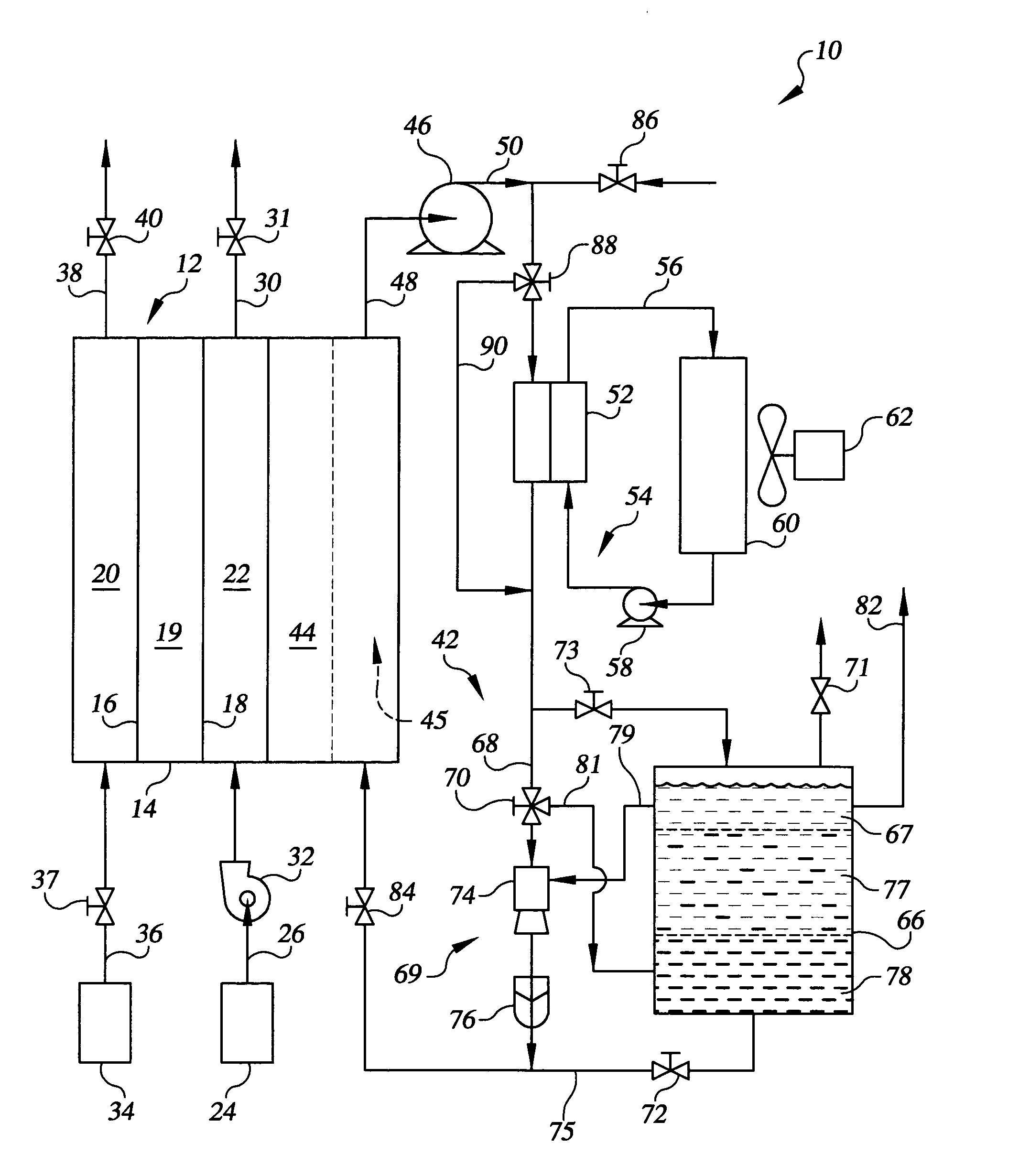
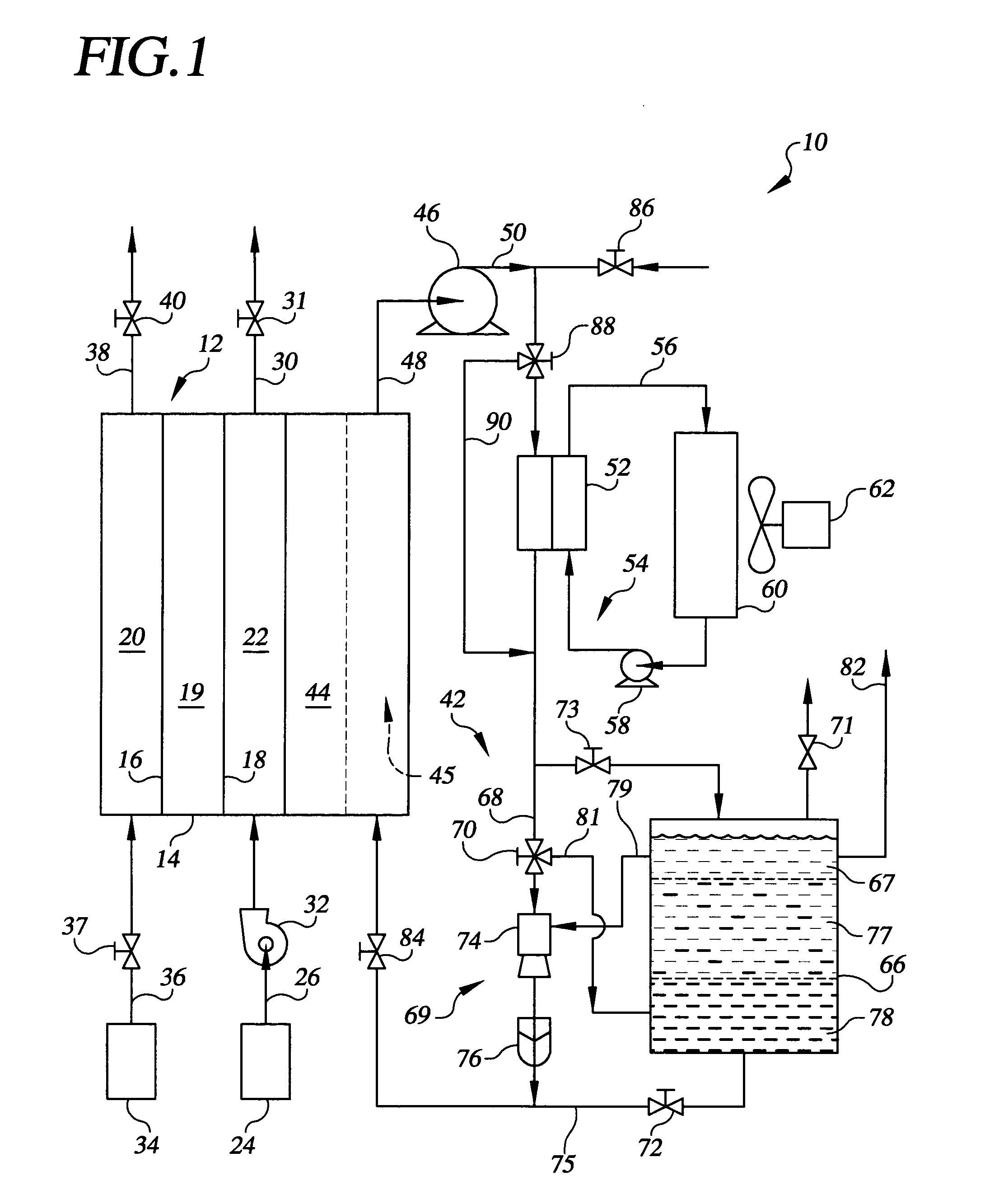
[0017] Referring to the drawings in detail, a freeze tolerant fuel cell power plant with a two-component mixed coolant of the present invention is shown in FIG. 1, and is generally designated by the reference numeral 10. The power plant 10 includes an electrical current producing fuel cell means for producing electrical current from reducing fluid and process oxidant reactant streams, such as a fuel cell 12. The fuel cell 12 includes a membrane electrode assembly (“MEA”) 14, including an anode catalyst 16 and a cathode catalyst 18 secured to opposed sides of an electrolyte 19, such as a well known proton exchange membrane (“PEM”). An anode flow field 20 is defined adjacent to the anode catalyst 16, and a cathode flow field 22 defined adjacent to the cathode catalyst 18. An oxidant supply 24 directs an oxidant, such as air, through an oxidant inlet 26 into the cathode flow field 22 so that the cathode flow field 22 directs the oxidant to flow past the cathode catalyst 18. The oxidant...


PUM

PropertyMeasurementUnit
volume percentaaaaaaaaaa

Abstract

A freeze tolerant fuel cell power plant (10) includes at least one fuel cell (12), a coolant loop (42) having a porous water transport plate (44) secured in a heat and mass exchange relationship with the fuel cell (12) and a coolant pump (46) for circulating a coolant through the plate (44) and for transferring water into or out of the plate (44) with the coolant. A coolant heat exchanger (52) removes heat from the coolant, and an accumulator (66) stores the coolant and fuel cell product water and directs the product water out of the accumulator (66). The coolant is a two-component mixed coolant liquid circulating through the coolant loop (42) consisting of between 80 and 95 volume percent of a low freezing temperature water immiscible fluid component and between 5 and 20 volume percent of a water component.

Description

TECHNICAL FIELD [0001] The present invention relates to fuel cell power plants that are suited for usage in transportation vehicles, portable power plants, or as stationary power plants, and the invention especially relates to a fuel cell power plant that utilizes a two-component mixed coolant consisting of a large proportion of a water immiscible fluid component mixed with a small proportion of a water component to cool the plant and manage water of the plant. BACKGROUND ART [0002] Fuel cell power plants are well known and are commonly used to produce electrical energy from hydrogen containing reducing fluid fuel and oxygen containing oxidant reactant streams to power electrical apparatus such as power plants and transportation vehicles. In fuel cell power plants of the prior art, it is known that product water generated by fuel cells of the plant is often managed and removed through porous water transport plates of a coolant system, as well as through evaporation and / or entrainmen...

Claims


Application Information

Patent Timeline
Patent Type & Authority Applications(United States)
IPC IPC(8): H01MH01M2/00H01M2/02H01M2/08H01M8/00H01M8/04H01M8/12
CPCY02E60/50H01M8/04029
Inventor BREAULT, RICHARD D.HAGANS, PATRICK L.SCHROOTEN, JEREMY A.
Owner INT FUEL CELLS
Why Eureka
Try Eureka