Coated nickel-containing powders, methods and apparatus for producing such powders and devices fabricated from same

a nickel-containing powder and nickel-containing technology, which is applied in the field of nickel-containing powders, can solve the problems of destroying the electrical properties of metals, increasing the fabrication cost of such devices, and relatively expensive noble metals, and achieves high crystallinity

Inactive Publication Date: 2005-05-12
CABOT CORP
View PDF99 Cites 93 Cited by
  • Summary
  • Abstract
  • Description
  • Claims
  • Application Information

AI Technical Summary

Benefits of technology

[0145] The excess carrier gas 238 that is removed in the aerosol concentrator 236 typically includes extremely small droplets that are also removed from the aerosol 108. Preferably, the droplets removed with the excess carrier gas 238 have a weight average size of smaller than about 1.5 μm, and more preferably smaller than about 1 μm and the droplets retained in the concentrated aerosol 240 have an average droplet size of larger than about 2 μm. For example, a virtual impactor sized to treat an aerosol stream having a weight average droplet size of about 3 μm might be designed to remove with the excess carrier gas 238 most droplets smaller than about 1.5 μm in size. Other designs are also possible. When using the aerosol generator 106 with the present invention, however, the loss of these very small droplets in the aerosol concentrator 236 will typically constitute no more than about 10 percent by weight, and more preferably no more than about 5 percent by weight, of the droplets originally in the aerosol stream that is fed to the concentrator 236. Although the aerosol concentrator 236 is useful in some situations, it is normally not required with the process of the present invention, because the aerosol generator 106 is capable, in most circumstances, of generating an aerosol stream that is sufficiently dense. So long as the aerosol stream coming out of the aerosol generator 102 is sufficiently dense, it is preferred that the aerosol concentrator not be used. It is a significant advantage of the present invention that the aerosol generator 106 normally generates such a dense aerosol stream that the aerosol concentrator 236 is not needed. Therefore, the complexity of operation of the aerosol concentrator 236 and accompanying liquid losses may typically be avoided.
[0146] It is important that the aerosol stream (whether it has been concentrated or not) that is fed to the furnace 110 have a high droplet flow rate and high droplet loading as would be required for most industrial applications. With the present invention, the aerosol stream fed to the furnace preferably includes a droplet flow of greater than about 0.5 liters per hour, more preferably greater than about 2 liters per hour, still more preferably greater than about 5 liters per hour, even more preferably greater than about 10 liters per hour, particularly greater than about 50 liters per hour and most preferably greater than about 100 liters per hour; and with the droplet loading being typically greater than about 0.04 milliliters of droplets per liter of carrier gas, preferably greater than about 0.083 milliliters of droplets per liter of carrier gas 104, more preferably greater than about 0.167 milliliters of droplets per liter of carrier gas 104, still more preferably greater than about 0.25 milliliters of droplets per liter of carrier gas 104, particularly greater than about 0.33 milliliters of droplets per liter of carrier gas 104 and most preferably greater than about 0.83 milliliters of droplets per liter of carrier gas 104.
[0147] One embodiment of a virtual impactor that could be used as the aerosol concentrator 236 will now be described with reference to FIGS. 26-32. A virtual impactor 246 includes an upstream plate assembly 248 (details shown in FIGS. 27-29) and a downstream plate assembly 250 (details shown in FIGS. 25-32), with a concentrating chamber 262 located between the upstream plate assembly 248 and the downstream plate assembly 250.
[0148] Through the upstream plate assembly 248 are a plurality of vertically extending inlet slits 254. The downstream plate assembly 250 includes a plurality of vertically extending exit slits 256 that are in alignment with the inlet slits 254. The exit slits 256 are, however, slightly wider than the inlet slits 254. The downstream plate assembly 250 also includes flow channels 258 that extend substantially across the width of the entire downstream plate assembly 250, with each flow channel 258 being adjacent to an excess gas withdrawal port 260.
[0149] During operation, the aerosol 108 passes through the inlet slits 254 and into the concentrating chamber 262. Excess carrier gas 238 is withdrawn from the concentrating chamber 262 via the excess gas withdrawal ports 260. The withdrawn excess carrier gas 238 then exits via a gas duct port 264. That portion of the aerosol 108 that is not withdrawn through the excess gas withdrawal ports 260 passes through the exit slits 256 and the flow channels 258 to form the concentrated aerosol 240. Those droplets passing across the concentrating chamber 262 and through the exit slits 256 are those droplets of a large enough size to have sufficient momentum to resist being withdrawn with the excess carrier gas 238.
[0150] As seen best in FIGS. 27-32, the inlet slits 254 of the upstream plate assembly 248 include inlet nozzle extension portions 266 that extend outward from the plate surface 268 of the upstream plate assembly 248. The exit slits 256 of the downstream plate assembly 250 include exit nozzle extension portions 270 extending outward from a plate surface 272 of the downstream plate assembly 250. These nozzle extension portions 266 and 270 are important for operation of the virtual impactor 246, because having these nozzle extension portions 266 and 270 permits a very close spacing to be attained between the inlet slits 254 and the exit slits 256 across the concentrating chamber 262, while also providing a relatively large space in the concentrating chamber 262 to facilitate efficient removal of the excess carrier gas 238.

Problems solved by technology

However, noble metals are relatively expensive and significantly increase the fabrication cost of such devices.
But most base metals have a tendency to oxidize when held in an oxygen-containing atmosphere at elevated sintering temperatures, thereby ruining the electrical properties of the metal and creating other problems in the device, such as delamination of the stacked layers.
This is believed to be due to the high processing costs and low production rates typically associated with spray pyrolysis.
Further, spray pyrolysis methods often produce hollow particles that are not sufficiently densified for most applications.

Method used


Image

  • Coated nickel-containing powders, methods and apparatus for producing such powders and devices fabricated from same
  • Coated nickel-containing powders, methods and apparatus for producing such powders and devices fabricated from same
  • Coated nickel-containing powders, methods and apparatus for producing such powders and devices fabricated from same

Examples


examples

[0290] A number of examples were prepared in accordance with the various embodiments of the present invention. Examples 1-5 are summarized in Table 1.

TABLE INickel Metal ExamplesREACTIONSAM-PRECURSORTEM-PLESOLUTIONCARRIER GASIMPACTORPERATURE10.5 M2 lpm N2No1000° C.Ni(NO3)25 lpm 7% H2 / N2(net 5% H2)20.5 M2 lpm N2yes1000° C.Ni(NO3)25 lpm 7% H2 / N2(8.5 μm(net 5% H2)cutoff)30.5 M2 lpm N2no 700° C.Ni(NO3)25 lpm 7% H2 / N2(net 5% H2)40.5 M5% H2 / N2no 850° C.Ni(NO3)25Ni(NO3)2 and2 lpm N2No1000° C.Pd(NO3)25 lpm 7% H2 / N2(net 5% H2)SAM-AVERAGE95% SIZEPOWDERSURFACEPLEPARTICLE SIZEDISTRIBUTIONDENSITYAREA11.2 μm0.4-2.5 μm7.13 g / cc2.4 m2 / g(80%)20.8 μm0.4-1.2 μm7.80 g / cc1.1 m2 / g(88%)31.8 μm0.4-3.5 μm—41.5 μm0.4-3.0 μm—5———

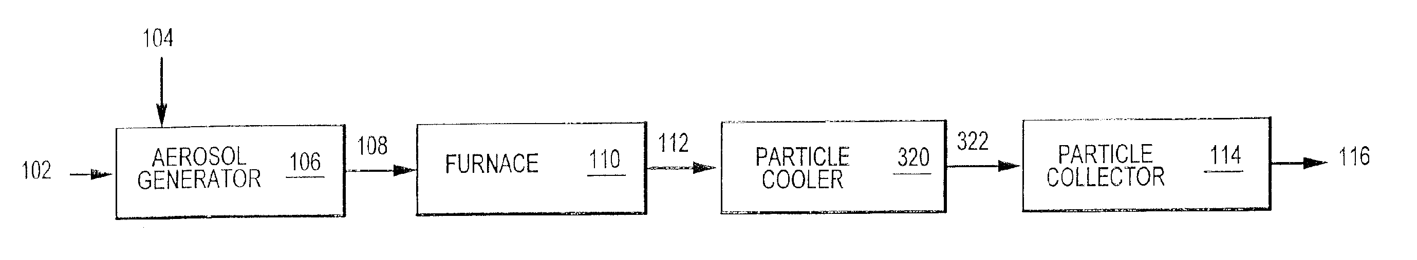
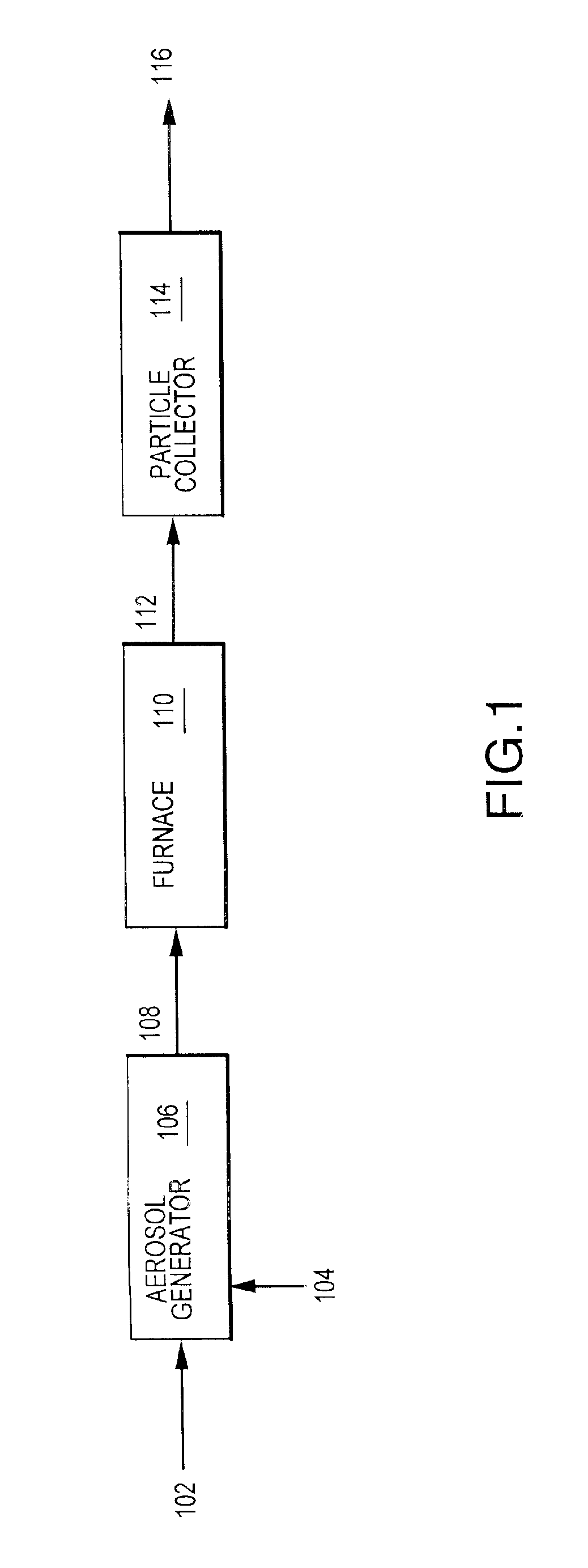
[0291] For each of Examples 1-5, an aqueous solution of 0.5 M Ni(NO3)2-6H2O was formed and an ultrasonic transducer generator operating at a frequency of about 1.6 MHz was utilized to produce an aerosol of liquid droplets from the solution. Nitrogen and hydrogen were used as a carri...


PUM

PropertyMeasurementUnit
thicknessaaaaaaaaaa
thicknessaaaaaaaaaa
thicknessaaaaaaaaaa

Abstract

Nickel powder batches including coated nickel-containing particles and methods for producing the same. The coated nickel-containing particles having have a small particle size, narrow size distribution and a spherical morphology. The present invention is also directed to devices incorporating the coated nickel-containing particles.

Description

CROSS-REFERENCE TO RELATED APPLICATIONS [0001] This application is a continuation application of U.S. patent application Ser. No. 09 / 991,270 filed Nov. 9, 2001, which is a divisional application of U.S. patent application Ser. No. 09 / 028,678 filed Feb. 24, 1998, now U.S. Pat. No. 6,316,100, which claims priority to U.S. Provisional Application No. 60 / 038,258 filed Feb. 24, 1997 and to U.S. Provisional Application No. 60 / 039,450 filed Feb. 24, 1997. The foregoing patent applications are incorporated herein by reference in their entirety.BACKGROUND OF THE INVENTION [0002] 1. Field of the Invention [0003] The present invention relates to nickel powders and to methods for producing such powders, as well as intermediate products and devices fabricated using the powders. In particular, the present invention is directed to powder batches of nickel particles with a small average particle size, well controlled particle size distribution, spherical morphology and high crystallinity. [0004] 2....

Claims


Application Information

Patent Timeline
Patent Type & Authority Applications(United States)
IPC IPC(8): B01J2/04B01J2/00B01J2/02B01J2/16B01J2/18B05B17/06B22F1/052B22F1/054B22F1/16B22F9/02B22F9/24B22F9/26B22F9/30B24B37/04B29B9/10C01B13/18C01B17/20C01G15/00C01G23/00C01G25/00C09G1/02C09K3/14C09K11/02C09K11/08C09K11/56C09K11/59C09K11/62C09K11/67C09K11/77C22C1/10C22C29/12C22C32/00H01B1/16H01C17/065H01G4/008H01J29/20H01L21/321H01L23/498H05K1/09
CPCB01J2/003B01J2/006B01J2/02B01J2/04B22F1/0014B22F1/0018B22F1/02B22F1/025B22F9/02B22F9/026B22F9/24B22F9/26B22F9/30B22F2998/00B22F2999/00B24B37/044B82Y30/00C01B13/185C01B17/20C01G15/006C01G23/003C01G23/006C01G25/00C01P2002/60C01P2002/70C01P2004/03C01P2004/32C01P2004/34C01P2004/50C01P2004/52C01P2004/61C01P2004/62C01P2004/80C01P2006/10C01P2006/60C01P2006/80C09G1/02C09K3/1436C09K3/1463C09K11/025C09K11/0805C09K11/0877C09K11/562C09K11/565C09K11/567C09K11/595C09K11/625C09K11/671C09K11/7718C09K11/7731C09K11/7734C09K11/7746C09K11/7771C09K11/7774C09K11/7789C09K11/7797C22C1/1026C22C29/12C22C32/0089H01G4/008H01G4/0085H01G4/30H01J29/20H01L21/3212H01L23/49883H01L31/022425H01L2224/29339H01L2224/8384H01L2924/09701H01M4/02H01M4/0421H01M4/366H01M4/38H01M14/005H01M2004/021H05K1/092Y02E10/50H01L2924/01019H01L2924/01079H01L2924/01327Y10T428/2991Y10T428/2982Y10T428/2998Y10T428/2993Y10T428/12181Y10T428/29B22F1/0048B22F2202/01B22F3/008B22F2202/11H01L2924/00H01G4/12H01L2924/203H01L2924/12044Y10T428/31678Y02E60/10Y02P10/25B22F1/054B22F1/052B22F1/16H01L2924/0002B22F10/10B22F1/065Y02P10/32
Inventor KODAS, TOIVO T.HAMPDEN-SMITH, MARK J.CARUSO, JAMESPOWELL, QUINT H.CHANDLER, CLIVE D.SKAMSER, DANIEL J.
Owner CABOT CORP
Why Eureka
Try Eureka