Ground fault detection system and method for inverter

a ground fault and detection system technology, applied in power conversion systems, arrangements resposes to fault current, electrical equipment, etc., can solve problems such as motor damage, secondary accidents such as fire, conventional ground fault detection methods cannot always handle ground faults, etc., to improve the operation reliability of inverters

Active Publication Date: 2005-05-12
LG IND SYST CO LTD
View PDF6 Cites 62 Cited by
  • Summary
  • Abstract
  • Description
  • Claims
  • Application Information

AI Technical Summary

Benefits of technology

[0018] Therefore, an object of the present invention is to provide a ground fault detection system and method for an inverter which can improve operational reliability of the inverter and prevent secondary accidents

Problems solved by technology

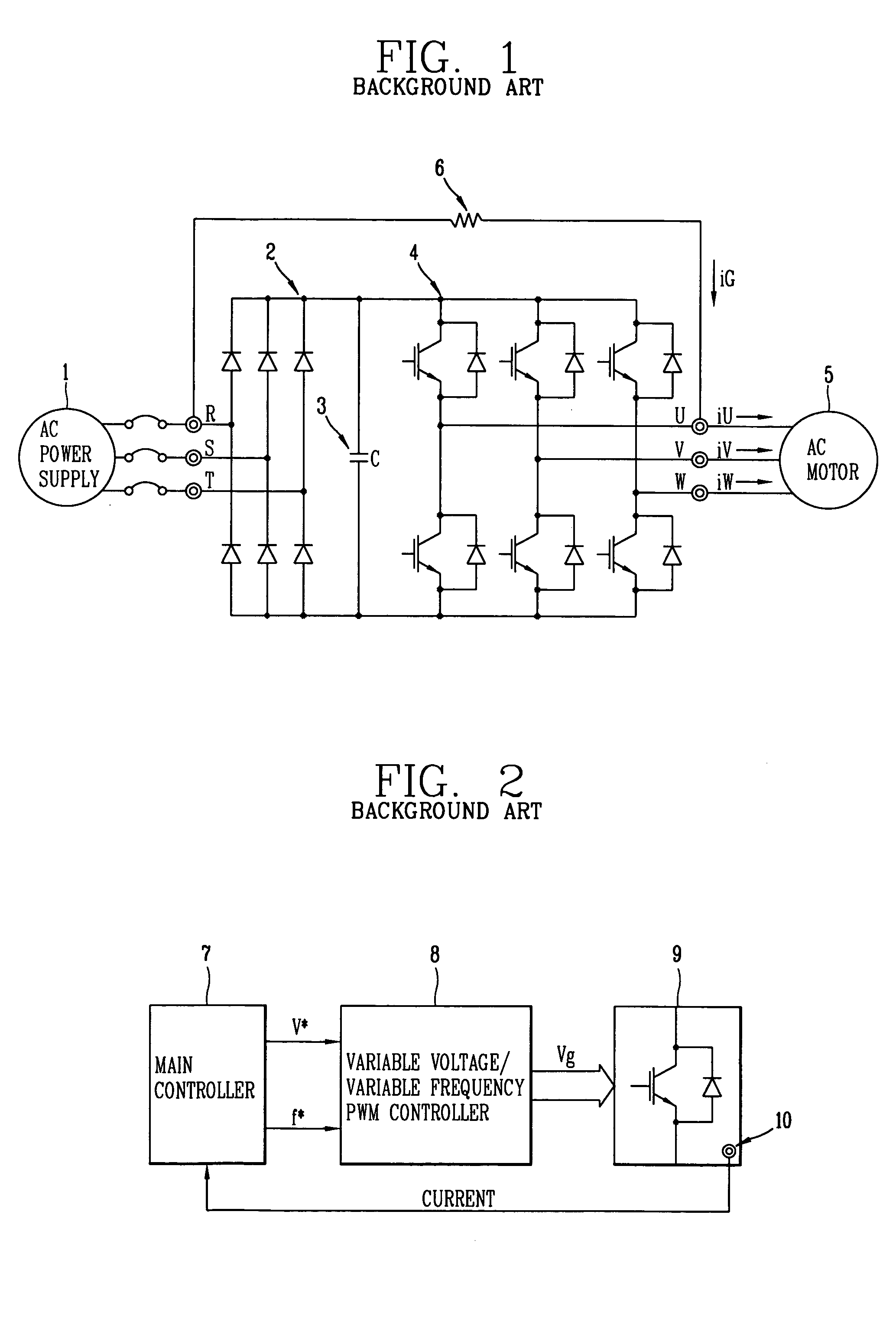
However, if an output line of the inverter contacts the earth due to lightening or aging, a large amount of current flows through the earth via a rectifier diode and a switching element of the inverter, which causes secondary accidents such as element damages and fire.
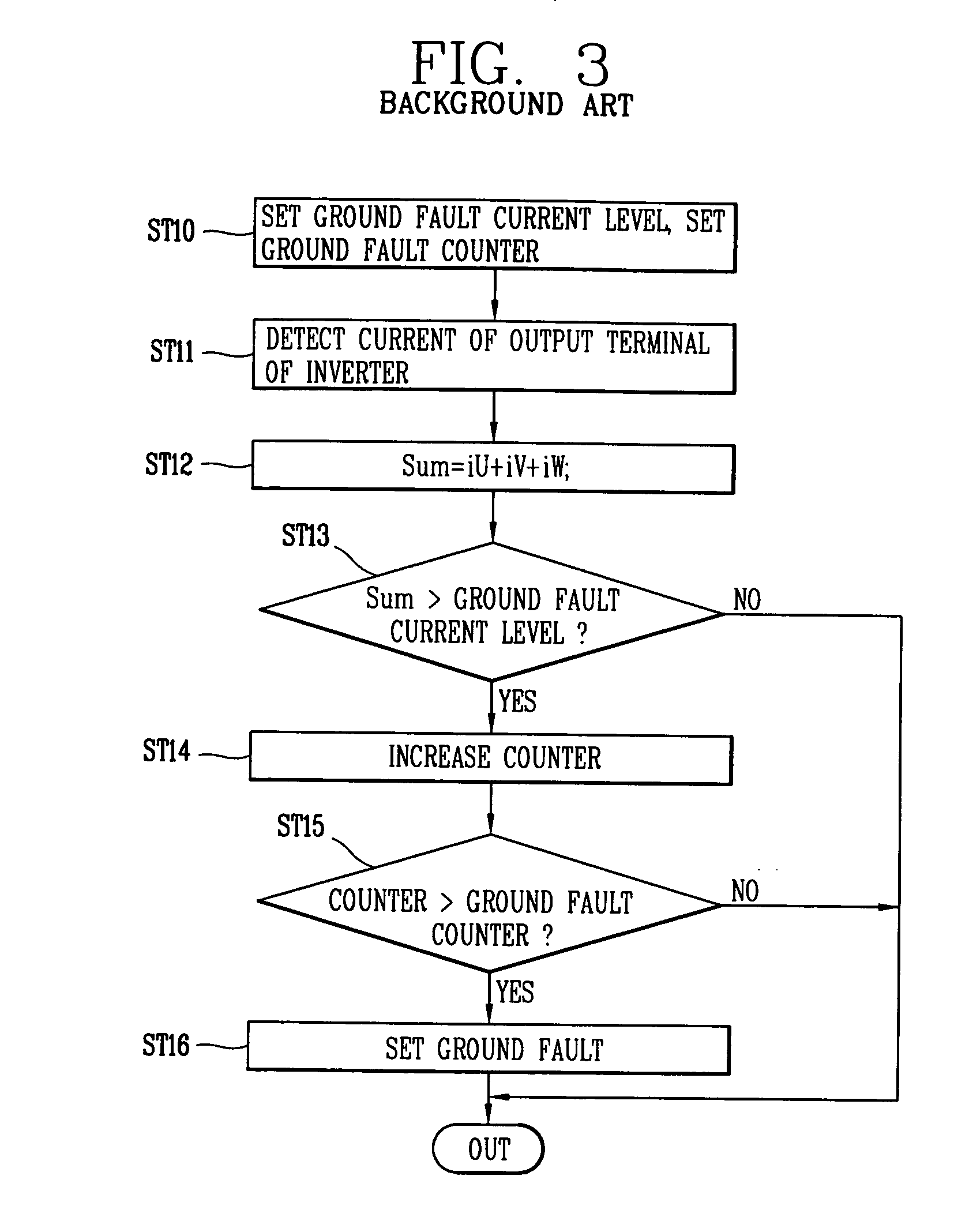
That is, although the phase current is seriously distorted due to an external ground fault and a large amount of ground fault current flows, the conventional ground fault detection method cannot always handle the ground fault.
However, if the ground faul

Method used


Image

  • Ground fault detection system and method for inverter
  • Ground fault detection system and method for inverter
  • Ground fault detection system and method for inverter

Examples


Embodiment Construction

[0030] Reference will now be made in detail to the preferred embodiments of the present invention, examples of which are illustrated in the accompanying drawings.

[0031]FIG. 5 is a structure diagram illustrating a ground fault detection system for an inverter in accordance with the present invention.

[0032] Referring to FIG. 5, the ground fault detection system for the inverter includes a converter 31 for converting an AC into a DC and outputting the DC, an initial charging resistor (R) 33 for preventing inflow of an inrush current in power supply, an electromagnetic contactor 32 for separating the initial charging resistor 33 from the circuit after the inrush current is restricted, a filter condenser 34 for smoothing the DC from the converter 31, a variable voltage / variable frequency PWM inverter 35 (hereinafter, referred to as ‘inverter’) including a control switching element (for example, transistor, MOSFET, IGBT, GTO, etc.), converting the DC into the AC, and outputting the AC, ...


PUM


Abstract

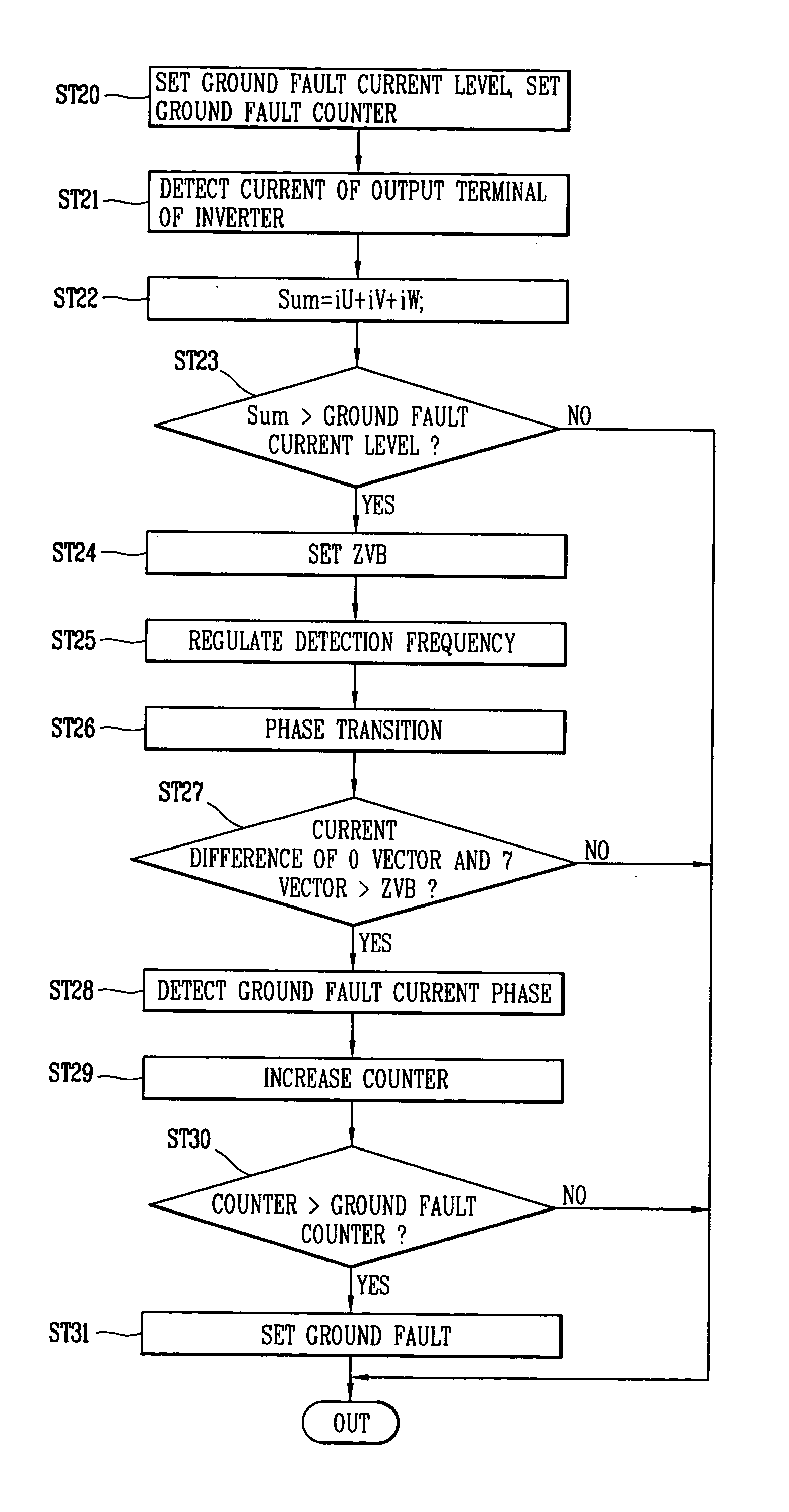
The present invention discloses a ground fault detection system and method for an inverter. The ground fault detection method for the inverter includes a reference value setting step for setting a reference value for estimating a ground fault current and a reference value for deciding a ground fault, a ground fault current estimation step for comparing a current value obtained by adding up current values flowing through each phase of an output terminal of the inverter with the reference value for estimating the ground fault current, and estimating generation of the ground fault current when the calculated current value is larger than the reference value, and a ground fault phase decision step for deciding the phase in which the ground fault has been generated on the basis of a current difference value between start and end points of 0 vector sections of each phase or between start and end points of 7 vector sections of each phase. Therefore, even if the ground fault occurs in an output line during the load operation or a power frequency of the inverter is similar to an output frequency, the ground fault detection system and method for the inverter detect the ground fault to improve operational reliability of the inverter.

Description

BACKGROUND OF THE INVENTION [0001] 1. Field of the Invention [0002] The present invention relates to a ground fault detection system, and more particularly to, a ground fault detection system and method for an inverter which can detect a ground fault generated between an output terminal of the inverter and the earth, and discriminate the phase in which the ground fault has been generated. [0003] 2. Description of the Background Art [0004] In general, an inverter is a driving apparatus for a variable speed motor which can efficiently control a speed and torque of the motor, by receiving power from a utility power supply, converting the power into a DC, converting the DC into a variable voltage variable frequency AC, and supplying the AC to the motor. The inverter reduces energy consumption and improves quality by precisely controlling the speed of the motor. Therefore, the inverter has been widely used for automatic facilities such as various air blowers, pumps, machine tools and fib...

Claims


Application Information

Patent Timeline
IPC IPC(8): H02H3/027H02H3/16H02M1/00H02M7/5387
CPCH02H3/027H02M7/53875H02M1/32H02H3/165H02M7/48
Inventor LEE, JEOUNG-PYO
Owner LG IND SYST CO LTD
Why Eureka
Try Eureka