Head slider and disk drive with the same

a head slider and disk drive technology, applied in the direction of maintaining the head carrier alignment, recording information storage, instruments, etc., can solve the problems of unstable floating position of the head slider, damage to any of the head sliders, and needs to be solved, so as to suppress the variations in the floating level of the slider, high squeezing force, and high resistance to impacts

Inactive Publication Date: 2005-05-19
WESTERN DIGITAL TECH INC
View PDF12 Cites 25 Cited by
  • Summary
  • Abstract
  • Description
  • Claims
  • Application Information

AI Technical Summary

Benefits of technology

[0031] This structure generates a positive pressure on the airflow control section and a mid level surface next to the low level surface by an effect of a squeezing force when the head slider comes close to the disk due to an external impact. The structure also generates a high squeezing force due to compression of the air at a boundary between the low level surface and the mid level surface, thereby suppressing variations in floating level of the slider attributable to the impact. This structure can thus provide the disk drive of steady quality with high resistance to impacts and high reliability.
[0032] As discussed above, the head slider and the disk drive equipped with the same according to this invention have the structure, in which the ABS of the head slider comprises three surfaces of different heights, the head slider is provided with the positive dynamic pressure generating section having equivalent height as that of the mid level surface in the vicinity of each of the both side edges lateral of the tracking width of the signal converting element, and the highest surface of the head mounting pad whereon the signal converting element is mounted is shaped asymmetrical with respect to the lateral center of the head slider in the tracking width direction of the signal converting element. In this structure, two positive dynamic pressure generating sections generate a large positive pressure when the disk drive receives an impact and the like from the outside and moves the head slider close to the disk especially during portable use, and this pressure prevents the head slider from colliding against the disk surface. This invention can thus provide an advantageous effect of preventing damages to any of the ABS of the head slider, the signal converting element mounted to the head slider, and the disk surface in which data are recorded. In addition, this structure can stabilize floating of the head slider regardless of the position of the head slider over the disk surface. The invention can improve the resistance to impacts of the disk drive during use and realize high reliability when it is equipped with the head slider having the ABS of the above configuration.

Problems solved by technology

However, any of the above head sliders of the prior art gives rise to a problem that the signal converting element mounted on the head slider comes into abnormally close to a surface of the disk due to instability of a floating posture of the head slider, because there is a difference in circling velocity of the disk relative to the head slider between the inner periphery and the outer periphery of the disk due to the difference in radius when a signal converting element mounted on the head slider makes a seeking operation across the inner periphery and the outer periphery, and variations of the circling velocity depending on a position of the head slider relative to a radial distance of the disk often cause the floating posture of the head slider unstable, and changes in angle of the head slider relative to the direction of airflow also cause the floating posture of the head slider unstable during the seeking operation of the signal converting element.
That is, if the disk drive unit receives an external disturbance of some kind such as a physical impact and the like, it causes the floating posture of the head slider unstable, thereby making the signal converting element mounted to the head slider come into abnormally close to the disk surface, or the head slider collides against the disk surface, resulting in damages to any of the head slider, the signal converting element and the disk.
Moreover, in the head slider of the structure having the dynamic pressure generating sections for generating a dynamic pressure on the surface facing the disk and the negative pressure generating sections provided within the same surface at the trailing side relative to the center thereof with respect to the rotating direction of the disk for generating a negative pressure, there is also a problem which needs to be solved.
That is, since this structure has a protruding pad serving as the dynamic pressure generating section in the central portion at the air outflow side of the ABS of the slider, it is unable to produce the maximum pressure on the element under a given floating position, and this structure is liable to collision of the head slider against the disk due to an external disturbance when the highest surface of the protruding pad comes to a point of the lowest floating height.
Furthermore, there are also other problems in the head slider of the structure comprising at least two of the dynamic pressure generating sections having shapes of longer dimensions in the direction generally orthogonal to the rotating direction of the disk than dimensions along the rotating direction, and arranged on the surface facing the disk along the rotating direction with the deep channel between them, and the first recesses formed in one of the dynamic pressure generating sections located at the trailing side of the rotating direction to provide the first raised portions along the direction generally orthogonal to the rotation direction and the second and third raised portions extending forward in the rotating direction from the both side ends of these first raised portions.
However, if these side portions are designed to produce the pressure at the given floating height, they give rise to the problems that (1) another pressure produced by an area of the element becomes relatively weak, and the element becomes liable to come in contact with the disk, that is, this structure has a poor followability of the element to undulation of the disk surface, and (2) the side portions of the slider are liable to came in contact to the disk when the floating height of the slider changes (i.e., by tilting or rolling).

Method used


Image

  • Head slider and disk drive with the same
  • Head slider and disk drive with the same
  • Head slider and disk drive with the same

Examples


first exemplary embodiment

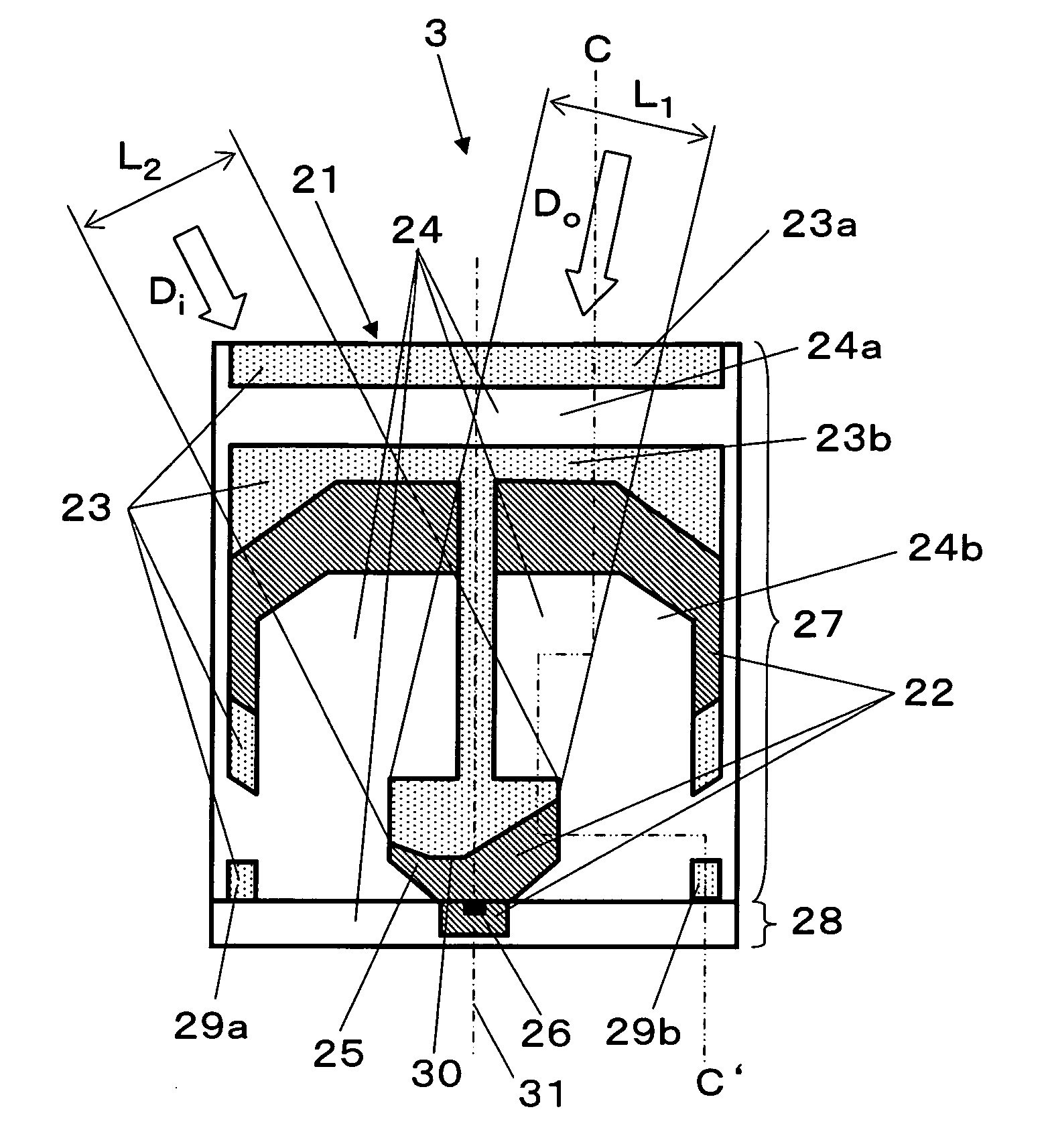
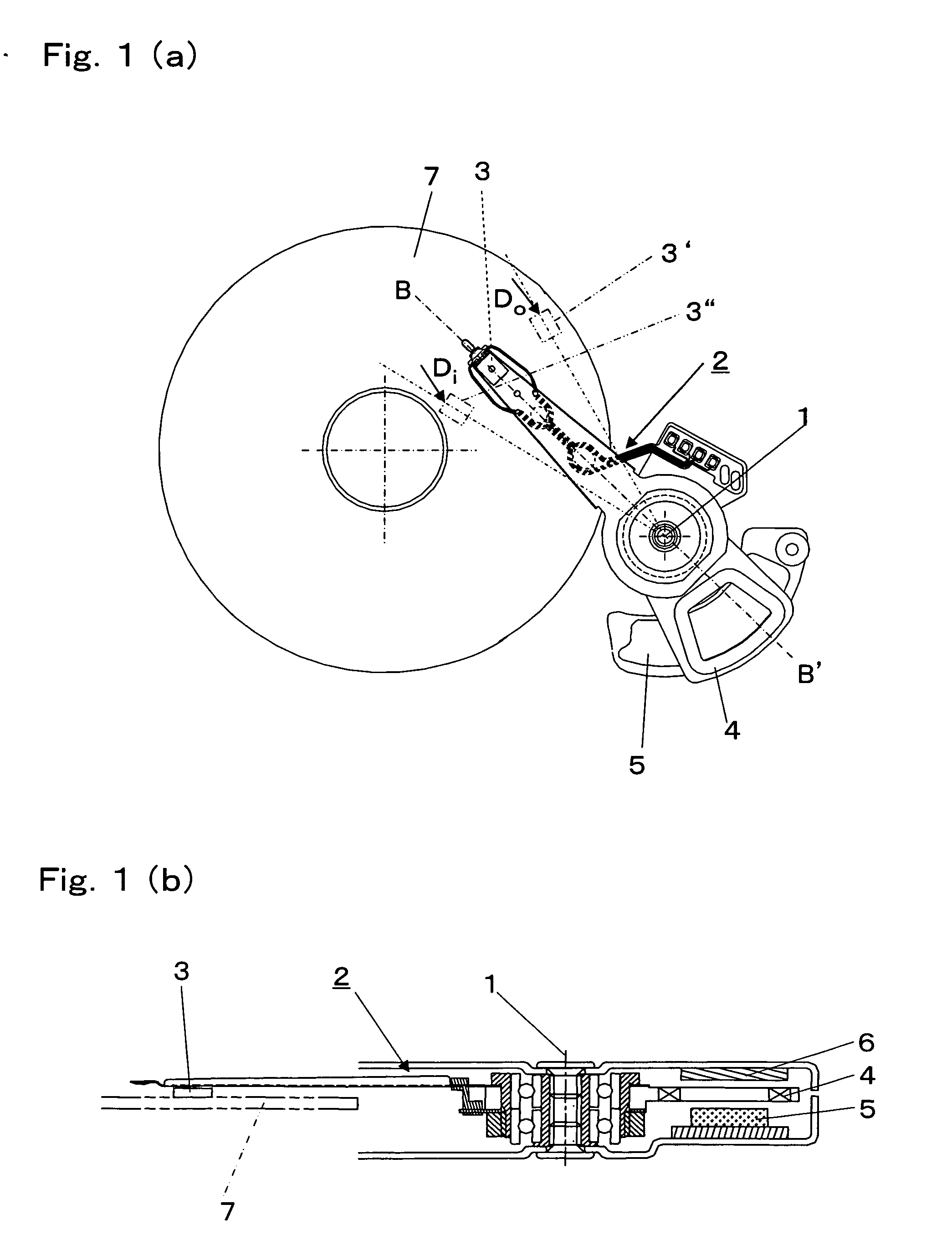
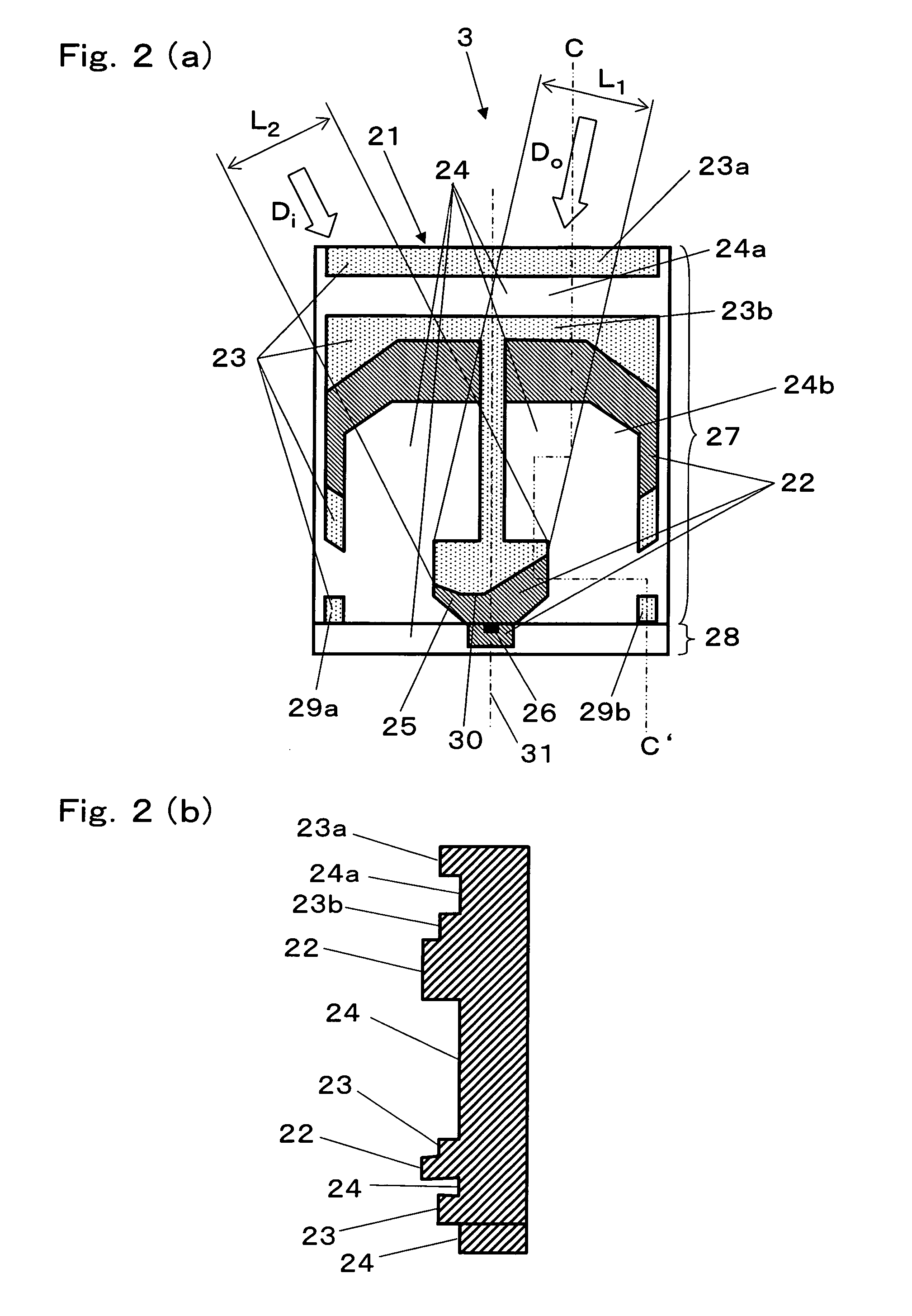
[0047]FIG. 1 and FIG. 2 are drawings used to illustrate a disk drive unit and a head slider equipped in the disk drive unit according to the first exemplary embodiment of the present invention. FIG. 1(a) is a plan view illustrating a structure of a major portion of the disk drive unit according to the first exemplary embodiment of the present invention, FIG. 1(b) is a sectioned view of the disk drive unit along a line B-B′ shown in FIG. 1(a), FIG. 2(a) is a plan view of a head slider according to the first exemplary embodiment, as observed from one side facing a disk, and FIG. 2(b) is a schematic view of the head slider sectioned along a line C-C′ shown in FIG. 2(a). Also, FIG. 3 is a plan view of another head slider used for a disk according to the first exemplary embodiment of the present invention, as is observed from one side facing the disk. In the following discussion, a magnetic disk unit such as a hard disk drive is used as an example for representing the disk drive unit.

[0...


PUM

PropertyMeasurementUnit
heightaaaaaaaaaa
weightaaaaaaaaaa
heightsaaaaaaaaaa

Abstract

A head slider is designed to prevent collision against a surface of a disk due to an external impact and the like while a device is in use to avoid damages on an air bearing surface (“ABS”) of the head slider and the surface the disk. This is achieved by a structure of the head slider which produces a large positive pressure on a positive dynamic pressure generating section when the head slider comes close to the disk. More specifically, the ABS of the head slider comprises three surfaces of different positional heights, and the positive dynamic pressure generating section having a height equivalent to a mid level surface of the second highest position is provided on a portion of the head slider made of a material of high brittleness at each of locations near both side edges lateral to a tracking width of a magnetic head. In addition, a head mounting pad bearing the magnetic head is so configured that a boundary between a high level surface in the highest position and a mid level surface is asymmetrical with respect to the lateral center of the head slider in a direction of the tracking width of the magnetic head.

Description

FIELD OF THE INVENTION [0001] The present invention relates to a floating type head used in a disk drive. In particular, the invention relates to a shape of an air bearing surface (may be referred to hereinafter as “air bearing surface” or “ABS”) of a head slider of the floating type head that stays low in floating level and is suitable for high density recording, while achieving a high resistance to impacts and superior reliability. The invention also relates to a disk drive with the same. BACKGROUND OF THE INVENTION [0002] Referring to FIG. 7, description is provided hereinafter of a shape of an ABS in a head slider of a floating type head used in a disk drive unit of the prior art. FIG. 7(a) is a plan view of the disk drive unit of the prior art as observed from the ABS side, and FIG. 7(b) is a sectional view of the same taken along a line A-A in FIG. 7(a). [0003] In FIG. 7, ABS 42 of head slider 41 faces a surface of a recording medium formed on a disk (not show in these figures...

Claims


Application Information

Patent Timeline
Patent Type & Authority Applications(United States)
IPC IPC(8): G11B5/60G11B21/21
CPCG11B5/6005G11B5/6082
Inventor UENO, YOSHIHIRODENG, ZHISHENG
Owner WESTERN DIGITAL TECH INC
Why Eureka
Try Eureka