
Electric storage augmentation of fuel cell system transient response

Active Publication Date: 2005-05-19
AUDI AG
View PDF7 Cites 12 Cited by
  • Summary
  • Abstract
  • Description
  • Claims
  • Application Information

AI Technical Summary

Benefits of technology

[0009] Objects of the invention include: a fuel cell power plant which can readily handle abrupt increases and decreases in load; increased capability of the fuel cell stack to handle abrupt decreases in load, without weakening the fuel cell structure; provision of reformers for converting hydrocarbon fuel to hydrogen for use as a fuel cell fuel which may utilize slowly responding sensors and valves; cost effective production and utilization of hydrogen in a fuel cell stack; and an improved apparatus for converting hydrocarbon fuel to electricity by means of a reformer and a fuel cell stack.
[0014] By handling shortages and excesses of electricity on the electrical side of the fuel cell stack, the production and / or application of hydrogen to the fuel cell stack can be regulated in a fashion which is much slower than the electrical load transients, without increased cost, endangering apparatus, or polluting the atmosphere, and the power conversion apparatus feeding a grid or other load can operate in a small range, with fewer constraints, and with more efficiency at lower cost.

Problems solved by technology

However, providing increased fuel volume in the fuel flow fields requires that the fuel channels be larger at the expense of thinner inter-channel ribs, which will decrease the strength of the fuel cell stack, and can lead to cracking of the fuel cells during assembly and other handling.
On the other hand, providing a larger volume for each fuel cell would usually be prohibitive in automotive applications, such as where a fuel cell power plant provides the electricity for an electric vehicle.
Thus, the use of fuel recycle to boost system efficiency comes at the expense of a reduction in increased-load transient capability.
In order to be able to consume the excess hydrogen, without causing equipment damage, the volume and burning capacity must be increased, which increases the overall volume and cost of the fuel cell power plant.
Tighter controls on the fuel control response rate may mitigate the problem of excess hydrogen, but it would never eliminate the problem entirely, and may add significant cost to a fuel cell system.
The aforementioned system will not satisfy the requirements of most modern applications of a fuel cell power plant upon which the demand varies continuously and significantly, such as a fuel cell power plant providing the power to an electric vehicle.

Method used


Image

  • Electric storage augmentation of fuel cell system transient response
  • Electric storage augmentation of fuel cell system transient response
  • Electric storage augmentation of fuel cell system transient response

Examples


Embodiment Construction

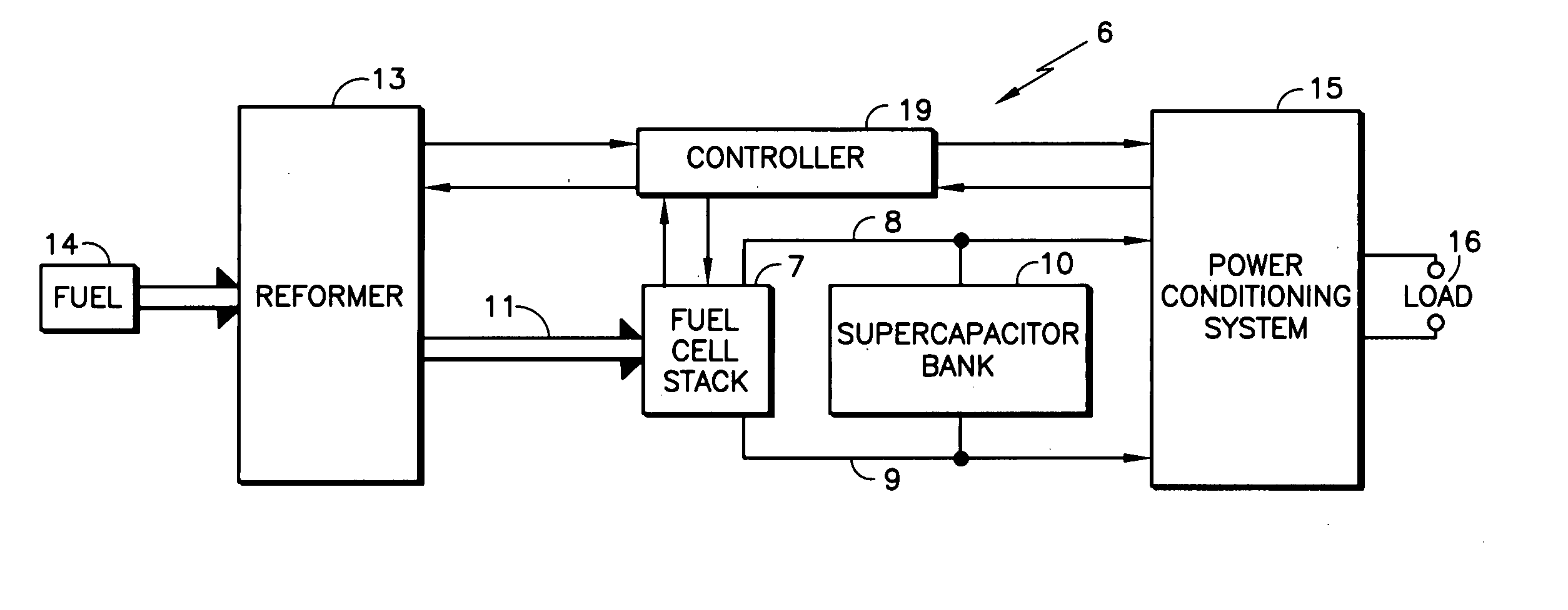
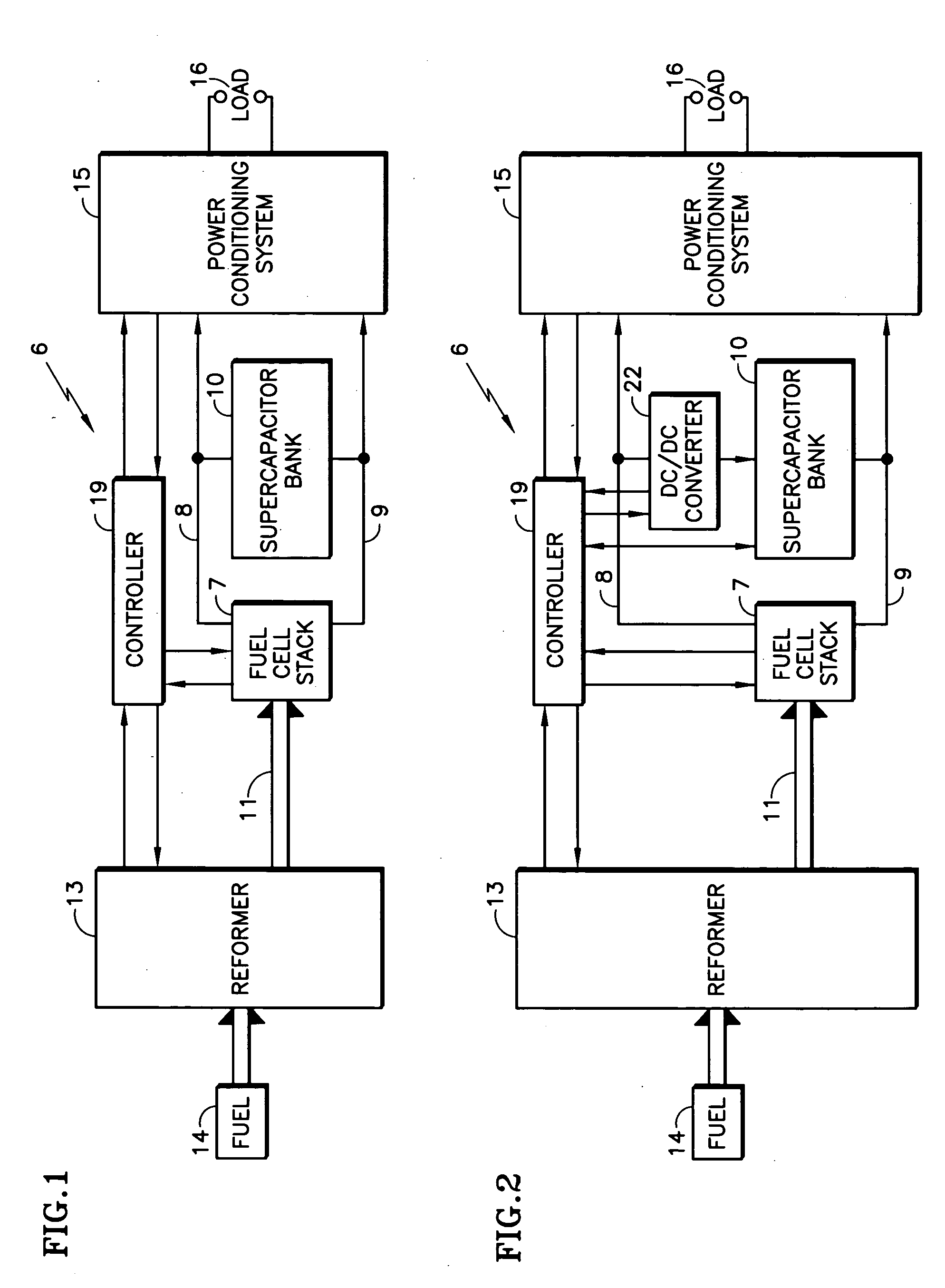
[0020] Referring to FIG. 1, a fuel cell power plant 6 includes a fuel cell stack 7 having electric output lines 8, 9 with an energy storage device, such as a supercapacitor bank 10, connected directly in parallel with the fuel cell stack 7 between the output lines 8, 9, in accordance with the invention. In the embodiment herein, the fuel cell stack 7 receives hydrogen-containing fuel in a conduit 11 from a reformer 13 that converts hydrocarbon fuel from a source 14, which may, for example, be a catalytic partial oxidizer reformer system such as those disclosed in copending U.S. patent application Ser. No. 10 / 369,359, filed Feb. 18, 2003, or any other reformer suitable to provide innocuous hydrogen-rich fuel to a fuel cell stack.

[0021] The power on the output lines 8, 9 is controlled for its intended use by a conventional power conditioning system 15, which applies the power to a load 16 which may be a grid, an electric vehicle motor, or any other load. As used herein, the term “loa...


PUM


Abstract

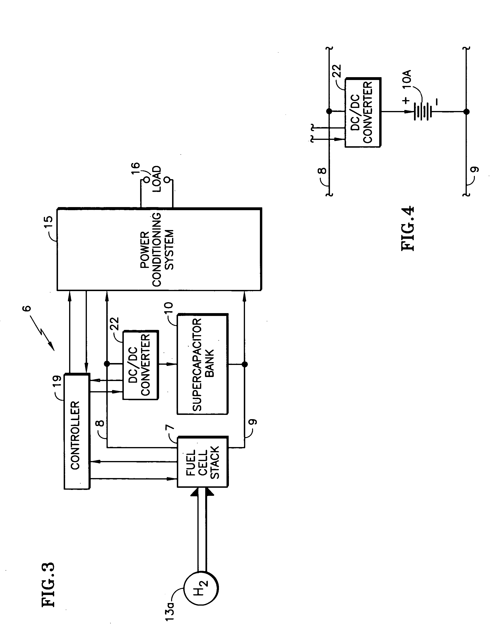
A fuel cell stack (7) with output lines (8, 9) has a bank of supercapacitors (10) or batteries (10a) connected across the output lines, either directly or through a DC / DC converter (22). The fuel cell stack receives fuel either from a reformer (13) or a source (13a) of hydrogen. Power is supplied through a power conditioning system (15) to a load (16), all under the control of a controller (19). The supercapacitors or batteries receive additional charge from excess power when there is a sudden decrease in the load, and provide charge to the output power lines (8, 9) when there is a sudden increase in load demand. In one embodiment, the voltage of the supercapacitors or batteries always follow the voltage of the fuel cell stack, thereby providing or receiving commensurate charge. With the DC / DC converter, the supercapacitors or batteries may be operated at voltages which are a multiple or a fraction of fuel cell stack voltage, and may have voltages boosted or bucked to aid in response to transients.

Description

TECHNICAL FIELD [0001] This invention relates to a fuel cell power plant having a bank of super capacitors connected electrically in parallel with the fuel cell stack, thereby to provide energy for increased load transients and to absorb energy during decrease load transients. BACKGROUND ART [0002] When a fuel cell stack assembly is operating normally and there is a sudden increase in the load, the capability of the fuel cell stack assembly to provide the required current is primarily a function of the amount of fuel resident in the fuel flow fields. If the fuel flow fields are designed so as to have a larger volume of fuel adjacent to the fuel cell membrane, the fuel cell stack assembly will have a greater increasing-load transient response capability. However, providing increased fuel volume in the fuel flow fields requires that the fuel channels be larger at the expense of thinner inter-channel ribs, which will decrease the strength of the fuel cell stack, and can lead to crackin...

Claims


Application Information

Patent Timeline
IPC IPC(8): H01MH01M8/00H01M8/04H01M8/06H01M16/00
CPCH01M8/04089H01M8/04544H01M8/04559H01M8/0488Y02E60/50H01M8/0612H01M8/0618H01M16/003H01M8/04888
Inventor CONVERSE, DAVID G.FREDETTE, STEVEN J.
Owner AUDI AG
Learn More