MIMO communication system

US20050107057A1Inactive Publication Date: 2005-05-19KK TOSHIBA

Image

  • MIMO communication system
  • MIMO communication system
  • MIMO communication system

Examples


Embodiment Construction

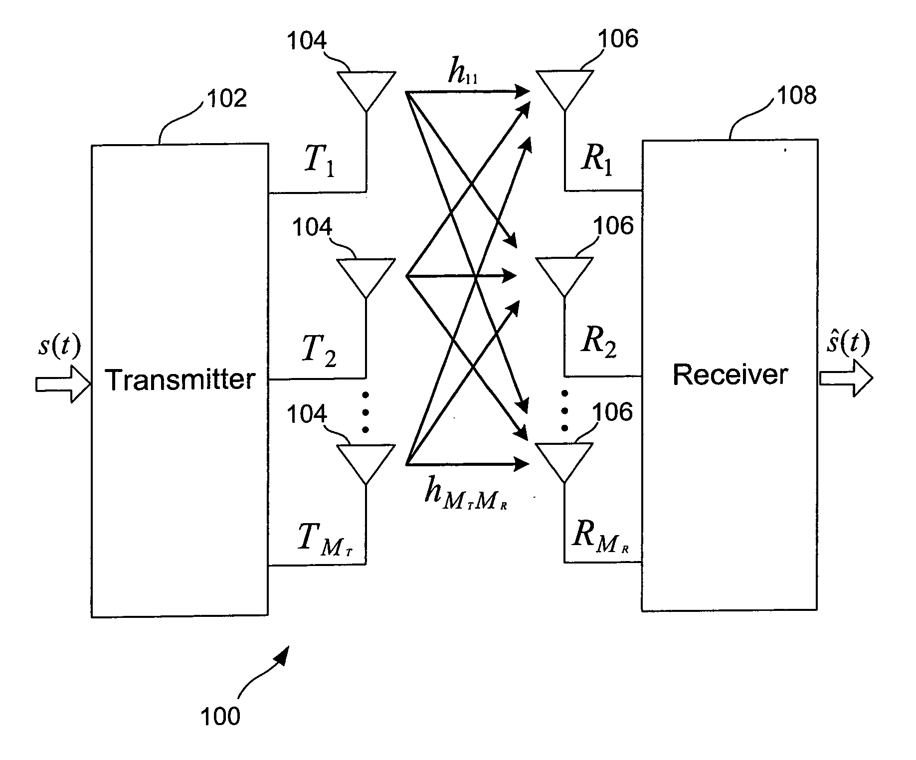
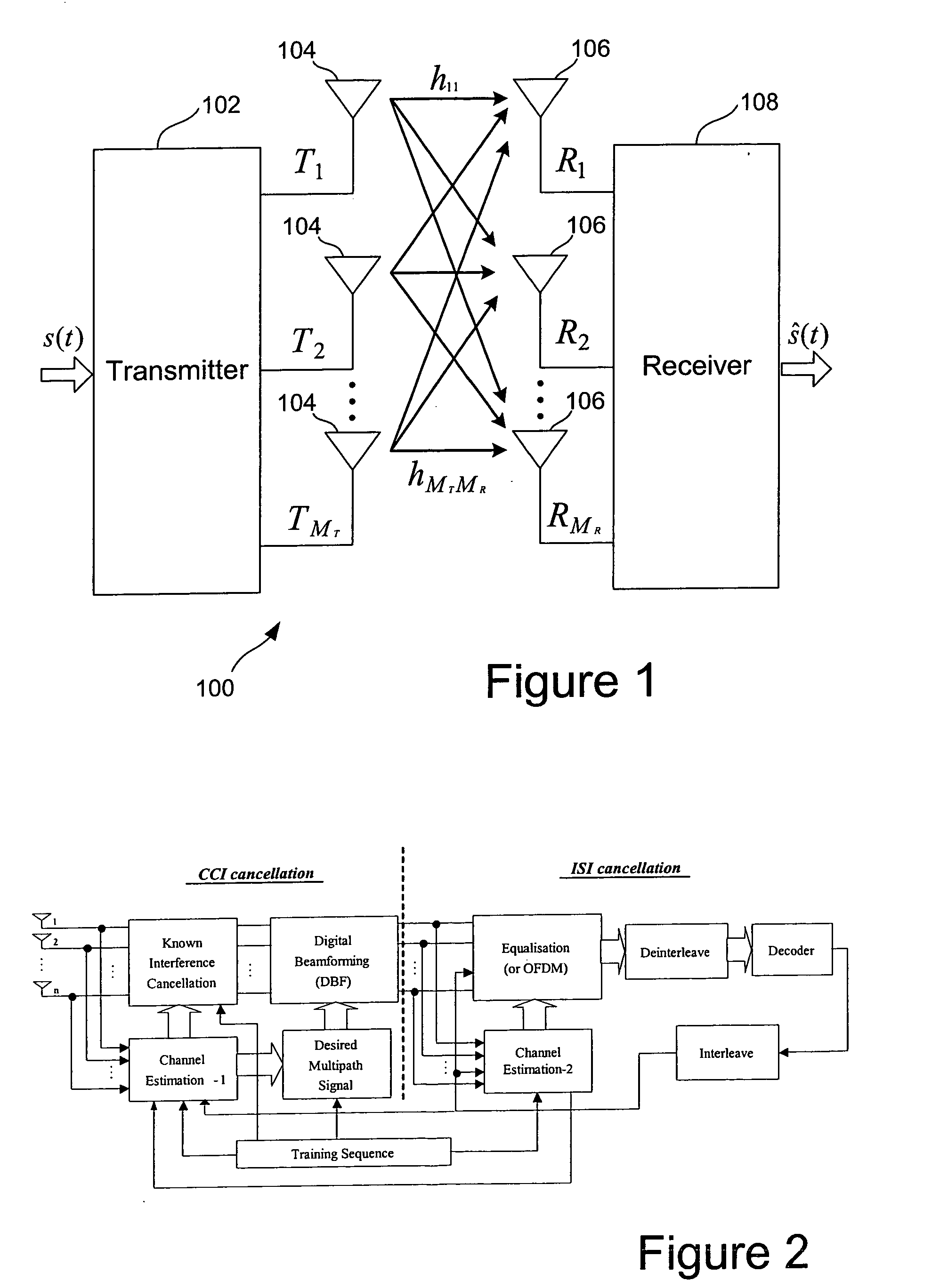
[0048]FIG. 1 shows the basic layout of a MIMO system 100. A data signal s(t) is passed to a transmitter 102 for encoding and splitting into separate streams corresponding to each of a plurality MT of transmission antennas 104. The signal from each antenna is then broadcast and received by the plurality MR of receive antennas 106 at the receiver. The path between each transmit antenna 104 and each receive antenna 106 can be modelled by a transfer function h and the overall channel transfer function of the system can be formed from the combination each of these transfer functions to define a function of matrix H. At the receiver 108, the signals from each antenna are extracted and the receiver applies the inverse H−1 of the channel transfer function to the received signals to extract the original transmission signals.

[0049] In order to apply the function H−1, the receiver must first determine the channel transfer function H or an estimate of it. This is normally done by having the tr...


PUM


Abstract

The invention provides a generic and comprehensive architecture to optimise several space-time adaptive algorithms and their applications for both CCI and ISI interference cancellation for MIMO systems. The basic idea of this invention is to optimise space-only processes and time-only processes and their combination to take account of the varying affects of CCI and ISI in a given environment. This maximises the efficiency of adaptive algorithms. The invention is targeting on unknown CCI or co-antenna interference of other operating system at the same frequency band.

Description

FIELD OF THE INVENTION [0001] The present invention relates to digital communication systems and in particular to multiple antenna systems using the multiple-input multiple-output (MIMO) system. BACKGROUND OF THE INVENTION [0002] As the demands on wireless communications continue to increase, the need for ever higher data throughput capacity rises. Various schemes have been proposed to maximise the amount useable bandwidth and to use the available bandwidth as efficiently as possible. [0003] Co-channel interference (CCI) and inter-symbol interference (ISI), which are the two major interference sources in wireless communication, differ from each other in many ways. Two major differences lie in the imbalance of energy and the different characteristics they have in the spatial and temporal domains. [0004] Beamforming is an effective way of excluding interference emanating from a direction other than that of the desired transmitter. This has conventionally been used for narrowband appli...

Claims


Application Information

Patent Timeline
19 May 2005
Publication
US20050107057A1
IPC
H04J99/00; H04B1/707; H04B7/08; H04L25/02; H04L25/03
CPC
H04B7/0845; H04B7/086; H04B7/0891; H04L2025/03375; H04L25/0236; H04L25/03006; H04L25/0204
Inventors
SUN, YONG