
Optical glass

Inactive Publication Date: 2005-05-19
OHARA
View PDF5 Cites 36 Cited by
  • Summary
  • Abstract
  • Description
  • Claims
  • Application Information

AI Technical Summary

Benefits of technology

[0023] Studies and experiments made by the inventor of the present invention for achieving the above described object of the invention have resulted in the finding, which has led to the present invention, that by adding specific amounts of SiO2, B2O3, La2O3, Gd2O3, Li2O and F, an optical glass which has optical constants within the specific range, a low glass transition temperature (Tg), excellent internal quality and is suitable for reheat press molding or precision press molding.

Problems solved by technology

An optical glass which contains a large amount of rare earth oxides such as lanthanum oxide generally has a poor defoaming property and hence there is general tendency toward taking a long period of melting time for defoaming.
Accordingly, optical glasses containing a large amount of rare earth oxides such as lanthanum oxide tend to have insufficient internal quality such as bubbles and inclusions.
Since, however, As2O3 is a material which is detrimental to the environment, As2O3 has not been used recently.
In producing glass pressings by reheat press molding, a very high temperature is required and, therefore, a heat treating furnace is deteriorated in a relatively short period of time with resulting adverse effect to a stable production.
In obtaining glass moldings such as aspherical lenses by precision press molding, it is necessary to press lens performs which have been softened by heating in a high temperature environment for transferring the shape of the high precision molding surface of the mold to the lens performs and, therefore, the mold used for such precision press molding is subjected to a high temperature and, moreover, a high pressing force is applied to the mold.
Hence, in heating and softening the lens performs and press molding the lens performs, the molding surface of the mold tends to be oxidized or eroded, or a release film provided on the molding surface tends to be damaged with the result that the high precision molding surface of the mold cannot be maintained or the mold itself tends to be damaged.
In such a case, the mold must be replaced and, as a result, frequency of replacement of the mold increases and production of products at a low cost in a large scale thereby cannot be achieved.
Since, however, this glass contains very expensive HfO2 as an essential component, the production cost of the glass is so high that it is not commercially practicable.
Since, however, this optical glass contains very expensive Lu2O3 as an essential component, the production cost of the glass is so high that it is not commercially practicable.
Since, however, SnO2 which is an essential component becomes metal tin when the melting atmosphere becomes a reduction state and is alloyed with platinum used in the melting apparatus thereby causing erosion which is likely to lead to leaking of glass.
Hence, this glass is not commercially practicable.
Since, however, this glass requires a high melting temperature of 1350° C. to 1600° C. in refining and homogenizing the glass, inclusions tend to occur in this glass.
Further, although there are examples containing alkali oxides which can be melted at a relatively low temperature among specifically disclosed glasses in this publication, these glasses of the specific examples contain As2O3 which is detrimental to the environment.
However, all glasses but one that are specifically disclosed in this publication contain As2O3 which is detrimental to the environment.
Since glasses having optical constants within the above described specific range disclosed specifically in this publication contain As2O3 and, therefore, this glass is not desirable from the standpoint of environmental protection.
Moreover, this glass has the disadvantage of producing inclusions.
However, glasses specifically disclosed in these publications do not have optical constants within the above described specific range and, therefore, cannot satisfy requirements for the optical design described above.

Method used


Image

  • Optical glass

Examples


examples

[0119] Description will now be made about examples of the present invention. It should be noted that the scope of the present invention is not limited by these examples.

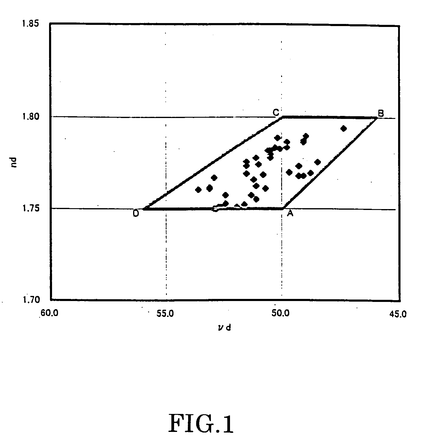
[0120] Compositions of examples of the present invention (Example No. 1 to No. 53) are shown in Tables 1 to 6 together with refractive index (nd), Abbe number (νd), glass transition temperature (Tg) and result of foreign matter rating (Class) of these examples. In the tables, composition of the respective components is expressed in mass %.

[0121] Likewise, compositions of comparative examples of the present invention (No. A to No. F) are shown in Table 7 together with refractive index (nd), Abbe number (νd), glass transition temperature (Tg) and result of foreign matter rating (Class) of these comparative examples.

TABLE 1Example No.12345678910SiO24.544.584.594.582.032.925.462.412.412.72B2O324.2023.3920.8121.7921.8625.6422.6925.7425.7425.74Y2O31.231.231.231.231.23La2O329.8128.1926.5727.7025.7330.2130.2133.2731.7430...


PUM

PropertyMeasurementUnit
Volumeaaaaaaaaaa
Glass transition temperatureaaaaaaaaaa

Abstract

An optical glass having a refractive index (nd) and Abbe number (νd) within a range enclosed with a border line consisting of straight lines connecting point A (nd being 1.75 and νd being 50.0), point B (nd being 1.80 and νd being 46.0), point C (nd being 1.80 and νd being 50.0) and point D (nd being 1.75 and νd being 56.0) in the order of the point A, the point B, the point C, the point D and the point A in x-y rectangular coordinates in which x coordinate represents Abbe number (νd) and y coordinate represents refractive index (nd), including refractive index (nd) and Abbe number (νd) on the border line except for the straight line connecting the point A with the point D and the straight line connecting the point B with the point C, containing, as essential components, SiO2, B2O3, La2O3, Gd2O3, Li2O and F, and being substantially free of As2O3.

Description

BACKGROUND OF THE INVENTION [0001] This invention relates to an optical glass and, more particularly, to an optical glass having a low glass transition temperature (Tg) and high refractive index and low dispersion characteristics, having excellent internal quality of glass and being suitable for reheat press molding or precision press molding. [0002] One of characteristics required for an optical glass is an excellent internal quality (striae, bubbles and inclusions). The internal quality depends upon a glass composition in some cases and, in other cases, upon conditions of manufacturing the glass. For producing a highly homogeneous optical glass with a good yield in manufacturing an optical glass, a melting apparatus in which a part or whole of a portion which comes into contact with glass melt is made of platinum or platinum alloy is generally used. For example, a crucible, tank, stirring blade and axis made of platinum or platinum alloy are generally used. When melting of glass r...

Claims


Application Information

Patent Timeline
IPC IPC(8): G02B1/00C03C3/068
CPCC03C3/068
Inventor UEHARA, SUSUMU
Owner OHARA
Learn More