Assembly for wireless energy communication to an implanted device

Inactive Publication Date: 2005-05-19
DEUTSCHES ZENTRUM FUER LUFT & RAUMFAHRT EV
View PDF11 Cites 57 Cited by
  • Summary
  • Abstract
  • Description
  • Claims
  • Application Information

AI Technical Summary

Benefits of technology

[0011] In accordance with the invention the receiver coil is the same size as the transmitter coil and likewise comprises a large number of preferably t

Problems solved by technology

One major problem in achieving artificial organ or other implanted systems is their power supply.
Apart from this, the transmitter and receiver parts always need to be positioned precisely one above the other, otherwise the coupling quickly deteriorates.
The drawback of this assembly is

Method used


Image

  • Assembly for wireless energy communication to an implanted device
  • Assembly for wireless energy communication to an implanted device
  • Assembly for wireless energy communication to an implanted device

Examples


Example

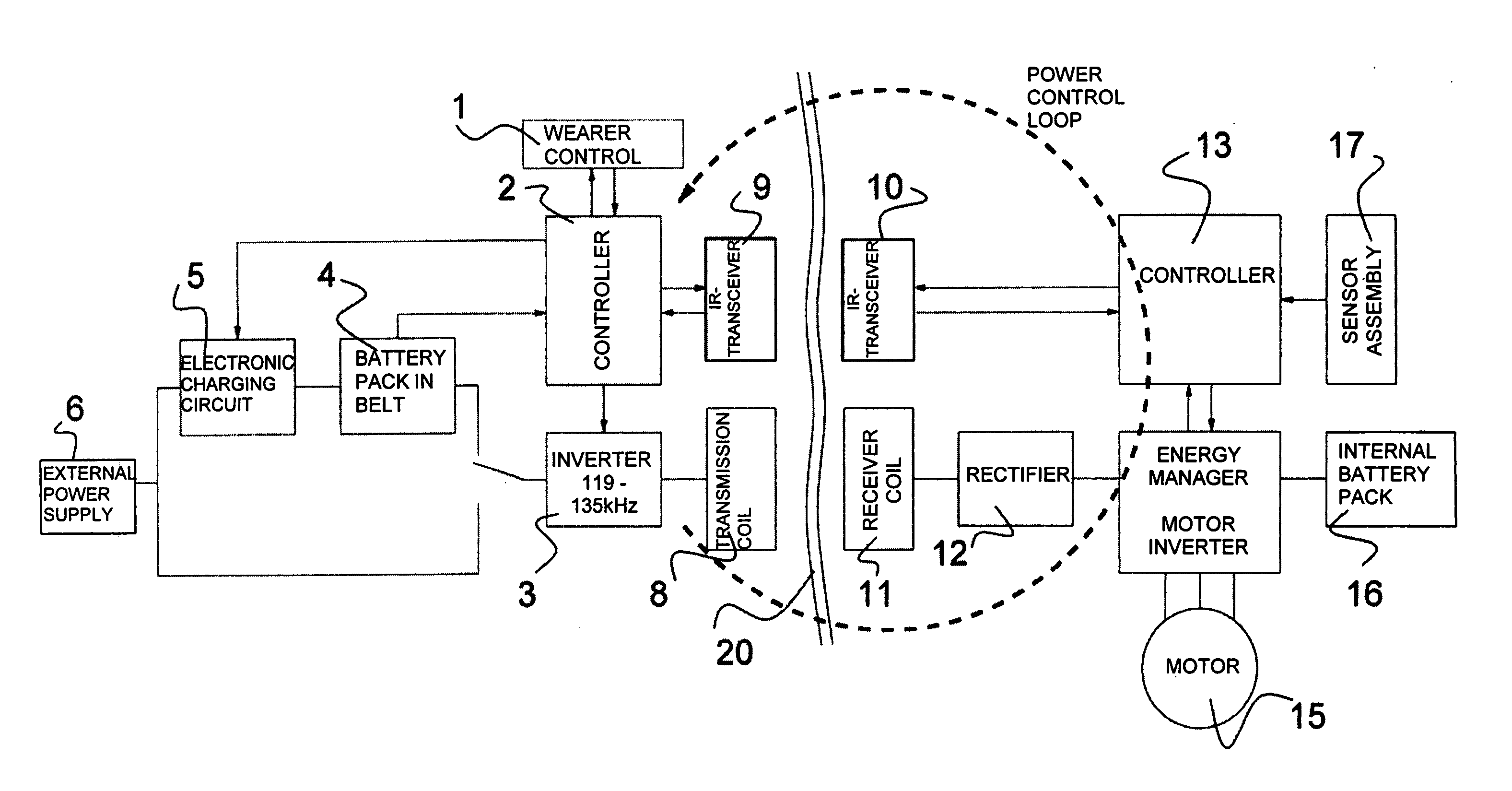
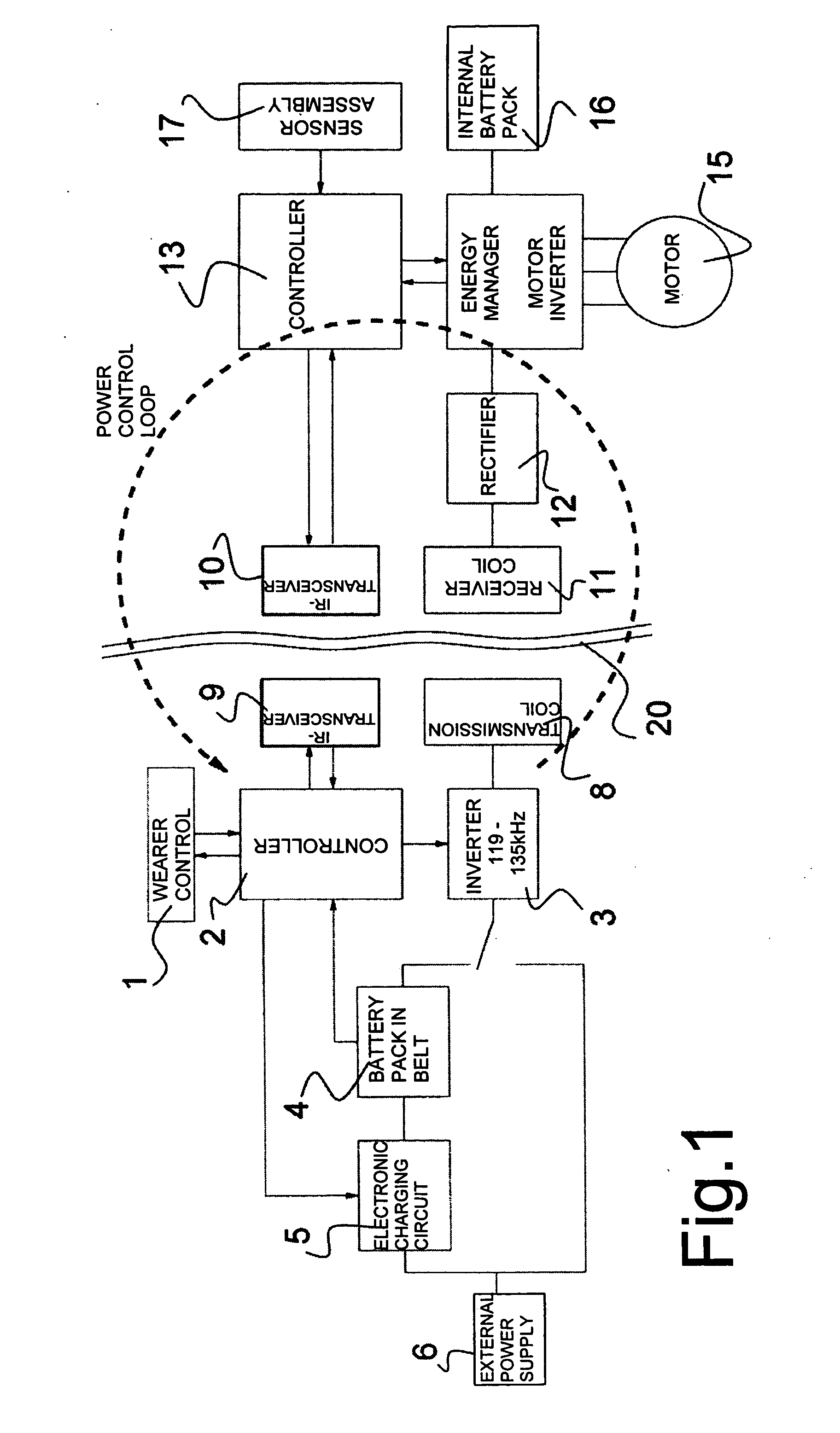
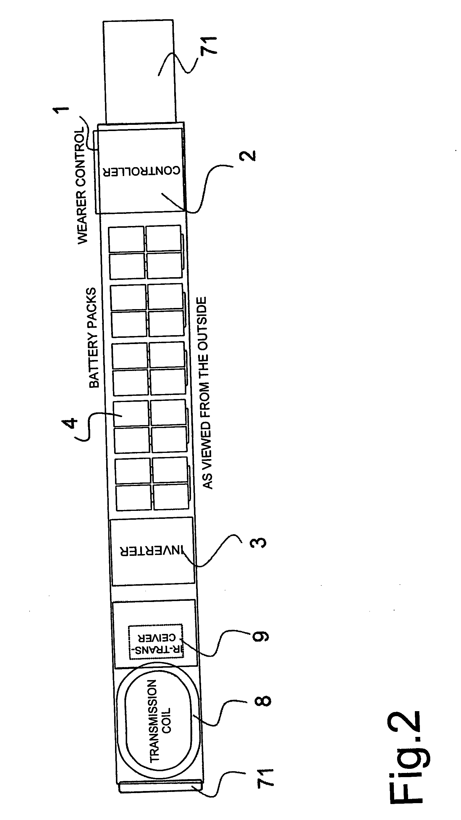
[0018] Referring now to FIG. 1 there is illustrated one embodiment of an assembly for wireless energy communication comprising a belt 7 (FIG. 2) accommodating a wearer control 1 to which a controller 2 is assigned for controlling an inverter 3, a transmission coil 8 as well as an infrared transceiver 9. Furthermore accommodated in the belt 7 for charging the battery pack 4 is an electronic charging circuit 5. By means of an external power supply 6 the battery pack 4 can be charged via the electronic charging circuit 5.

[0019] An implanted / implantable device comprises an infrared transceiver 10 to which a controller 13 as well as a sensor assembly 17 is assigned. Via the controller 13 an energy manager 14 and an inverter assigned to a motor 15 are controlled. The energy manager 14 is powered by an internal battery pack 16. The energy manager 14 is connected to a receiver coil 11 by a rectifier.

[0020] The components assigned to a power control loop are encircled by the broken line. F...


PUM


Abstract

An assembly for wireless energy communication to an implanted device comprises an external belt (7) accommodating a wearer control (1) followed by controller (2), a battery pack (4), an inverter (3), a transmission coil (8) connected in parallel by a plurality of capacitors, and an infrared transceiver 9. Provided furthermore is an implanted device comprising a receiver coil (11) having the same dimensions as the transmission coil (8), a rectifier following said receiver coil (11), an infrared transceiver (10) followed by a controller and an sensor assembly (17) assigned thereto as well as a battery pack (16) for powering said implanted device via an energy manager (14).

Description

FIELD OF THE INVENTION [0001] The invention relates to an assembly for wireless energy communication to an implanted device such as for instance a cardiac support system or artificial heart. PRIOR ART [0002] One major problem in achieving artificial organ or other implanted systems is their power supply. Where devices having a low power consumption such as for instance cardiac pacemakers are concerned, the energy can be supplied via batteries. For the supply of more powerful devices the following systems have hitherto found application: [0003] a direct supply wired through the abdominal wall or in the region of the neck, albeit with the risk of a permanent source of inflammation focused about the point of insertion and low acceptance by the wearer because of life quality impairment due to, for example, taking a shower or swimming no longer being possible, the risk of serious internal injuries due to inadvertent tugging of the wiring, etc, [0004] inductive systems making use of a hig...

Claims


Application Information

Patent Timeline
IPC IPC(8): A61N1/08A61N1/378G08C23/04H02J7/00H02J17/00
CPCA61N1/3787
Inventor GRUBER, ROBINSCHMID, THOMAS
Owner DEUTSCHES ZENTRUM FUER LUFT & RAUMFAHRT EV
Why Eureka
Try Eureka