
Method and system for providing cache set selection which is power optimized

a cache set and power optimization technology, applied in the field of instruction and data caches, can solve the problems of significant waste of operational power, power consumption of prediction logic, and inability to guarantee 100% predictability, and achieve the effect of high access speed

Inactive Publication Date: 2005-05-19
IBM CORP
View PDF9 Cites 63 Cited by
  • Summary
  • Abstract
  • Description
  • Claims
  • Application Information

AI Technical Summary

Benefits of technology

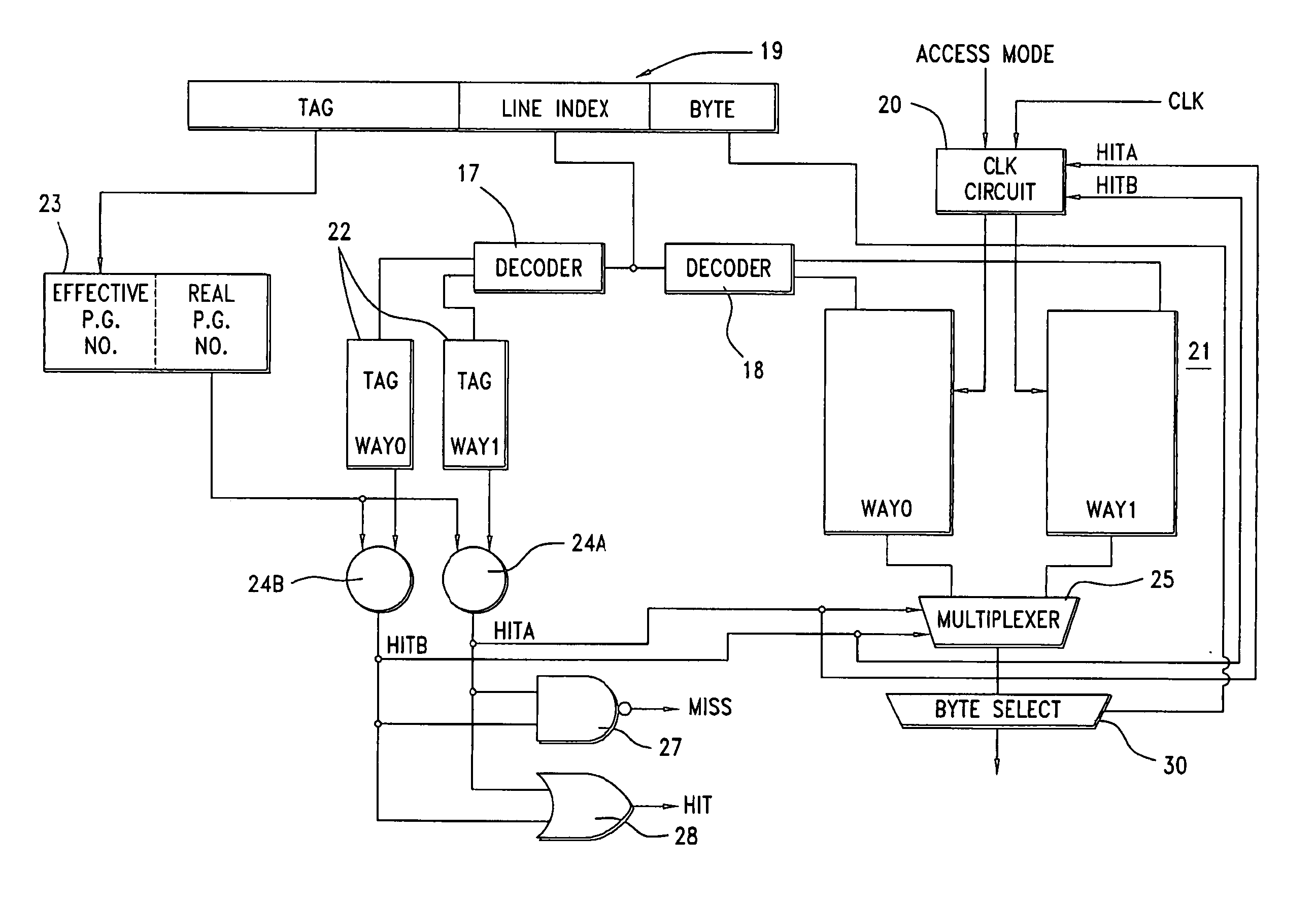
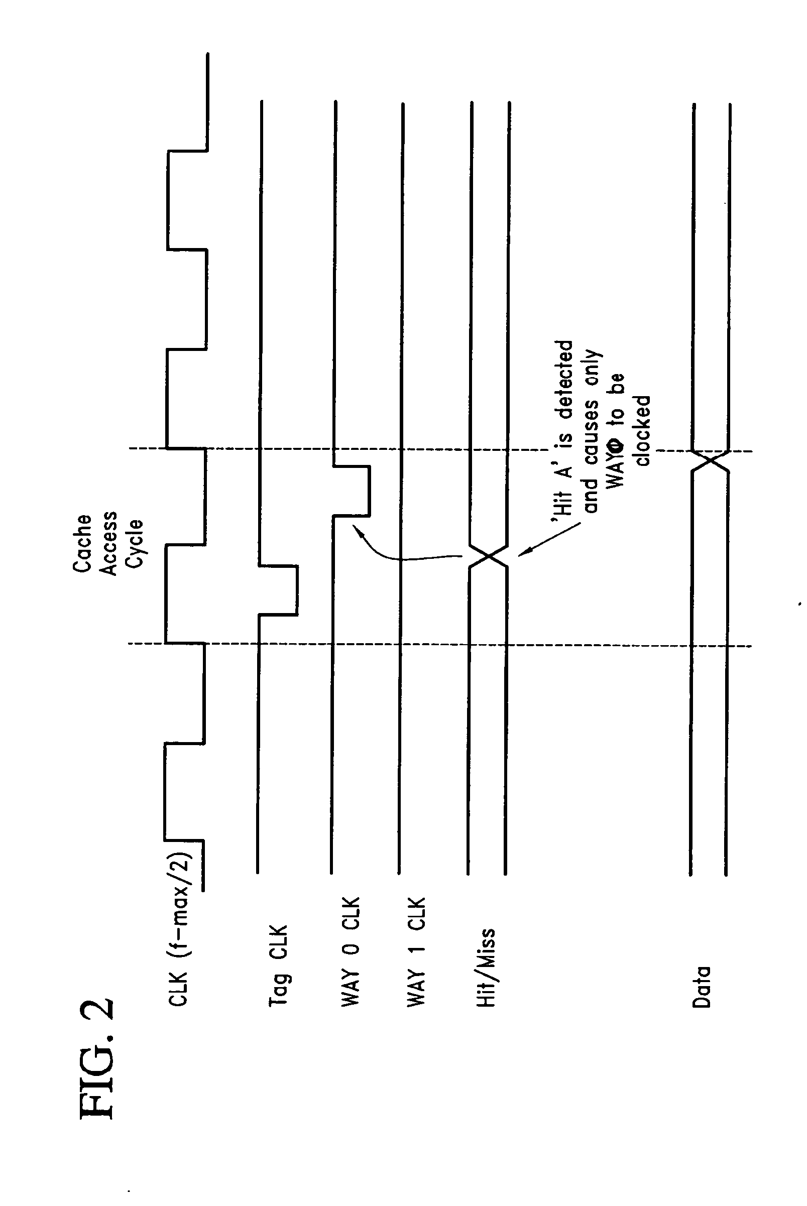
[0010] In accordance with a preferred embodiment of the invention, the system can be selectively operated at optimum access speed or at optimum power efficiency. The power efficiency mode may be implemented by detecting the access cycle frequency, and when the cycle time is adequate to allow a serial access of the cache way which contains the desired data, the system accesses at most only one way. Further, when the access frequency is higher, demanding a high access speed, both ways are clocked and a late select signal is used to select the access data from one the way containing the desired data.

Problems solved by technology

This represents a significant waste of operational power, particularly in battery operated devices such as cellular telephones which may use such microprocessor systems.
However, the prediction logic consumes power, and does not guarantee 100% predictability.
Accordingly, more cache misses occur on a false prediction with only a marginal savings in power consumption.
There are limitations, however, to these techniques particularly lowering the operating frequency, since providing adequate time to make a set decision, and then obtain the required data, mandates a reduced maximum frequency of operation.
However, the trade off between power savings and obtaining higher access speed is limited to normal prefetch and branch conditions.
Further, the access during normal prefetch operations are made over two cycles which significantly slows down the access process.

Method used


Image

  • Method and system for providing cache set selection which is power optimized
  • Method and system for providing cache set selection which is power optimized
  • Method and system for providing cache set selection which is power optimized

Examples


Embodiment Construction

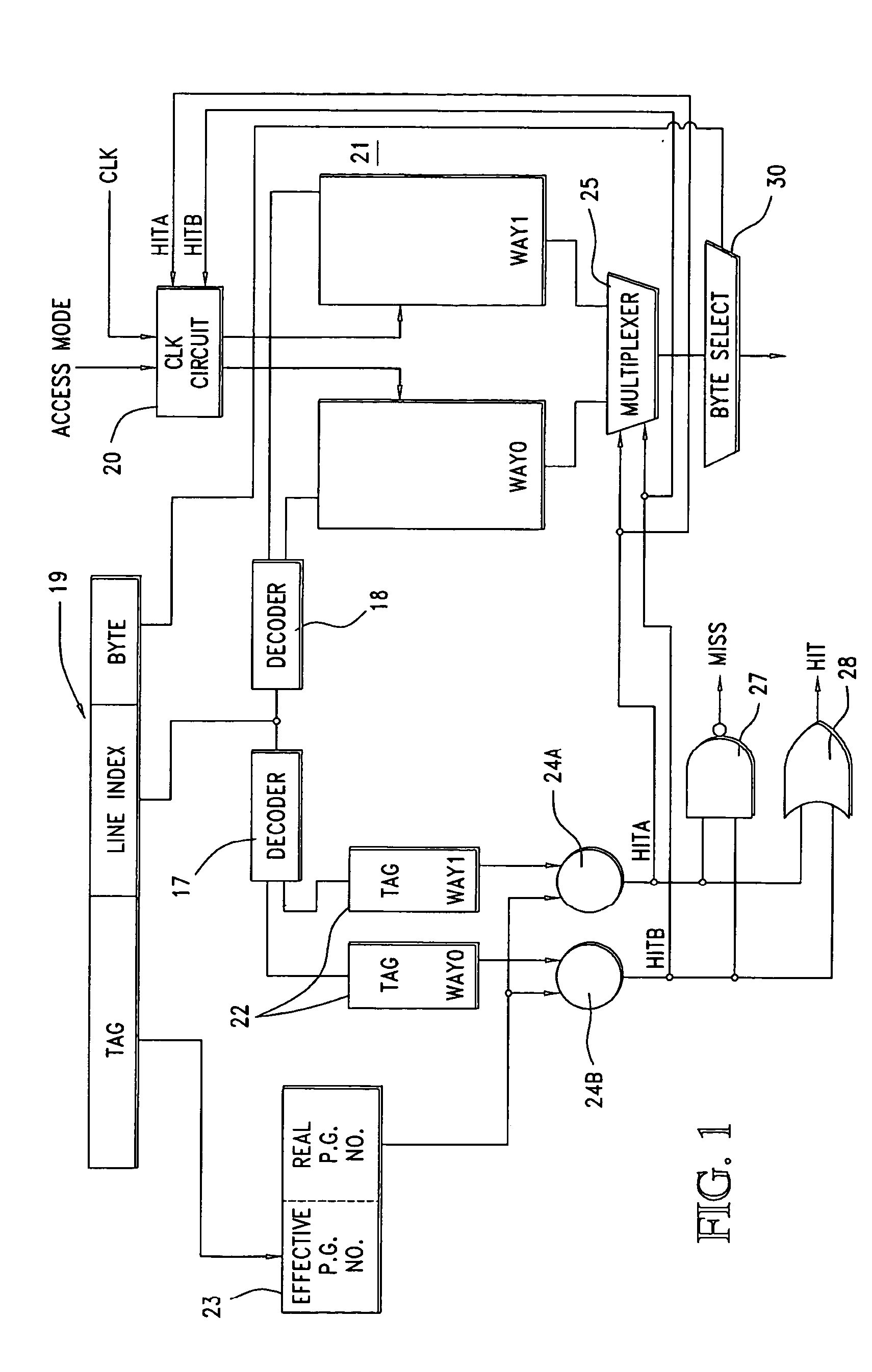
[0016] Referring now to FIG. 1, a two way associative cache 21 is shown. Way 0, and way 1 comprise two SRAMs which produce first and second data outputs to a select multiplexer 25. The data cache memory 21 stores instructions, or other data necessary for a microprocessing system. The specific use of the data is not relevant to the invention's operation.

[0017] The cache 21 is accessed from a register containing an effective address 19. The effective address contains data representing a tag associated with each line of memory in way 0 and way 1, a line index and a byte number. The Line Index portion of the effective address identifies which line of the ways is to be accessed, and the byte identification data permits selection of a particular byte contained in a line of data.

[0018] For each line or row of data contained in way 0 and way 1, a tag in a corresponding row of tag memories 22 is provided. The Line Index addresses both tag memories and both ways 0, 1. The tag data stored in...


PUM


Abstract

A system and method for accessing a data cache having at least two ways for storing data at the same addresses. A first and second tag memory store first and second sets of tags identifying data stored in each of the ways. A translation device determines from a system address a tag identifying one of the ways. A first comparator compares tags in the address with a tag stored in the first tag memory. A second comparator compares a tag in the address with a tag stored in the second tag memory. A clock signal supplies clock signals to one or both of the ways in response to an access mode signal. The system can be operated so that either both ways of the associative data cache are clocked, in a high speed access mode, or it can apply clock signals to only one of the ways selected by an output from the first and second comparators in a power efficient mode of operation.

Description

BACKGROUND OF THE INVENTION [0001] The present invention relates to instruction and data caches used in micro processor based computing systems for temporarily storing instructions and data. Specifically, a system and method are described which can address the associative cache in a high speed mode, or in a mode which conserves power. [0002] Computing systems, including micro-processor based systems, use a cache in conjunction with a main memory to hold data and / or instructions which are being processed. The cache comprises a memory where the temporary contents needed for processing are maintained so that the most recently used data from a main memory is located in a cache memory for rapid access by the micro-processor system. [0003] Cache memories are organized as set associative comprising sets of individual SRAMs which contain the desired data and which typically have common address lines. Each SRAM is referred to as a way, and in a two-way associative cache, common address lines...

Claims


Application Information

Patent Timeline
IPC IPC(8): G06F12/00G06F12/08
CPCG06F12/0846Y02B60/1225G06F2212/1028Y02D10/00
Inventor CORREALE, ANTHONY JR.DIEFFENDERFER, JAMES N.GOLDIEZ, ROBERT L.SPEIER, THOMAS P.REOHR, WILLIAM R.
Owner IBM CORP
Learn More